


TW-357 REV E
41
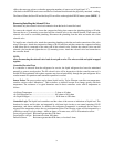
• Simulate an over fill by lowering the next thermistor into the LN2 . HIGH LEVEL alarm should sound
with 10 seconds.
• Re-install sensor assembly and thermocouple into sensor tube as before. Open supply valve on LN2
supply.
Indicates Low LN2 Supply
When the START FILL thermistor is uncovered, the controller calls for the fill solenoid valve to open. If the
STOP FILL thermistor is not covered with LN2 in the pre-determined amount of time, the controller is
programmed to interpret this as a LN2 supply shortage.
1. Check contents gauge and pressure gauge of supply cylinder. Both liquid contents and pressure (15 to 22
psi) are required to complete a fill.
2. Confirm that no other transfer hose or apparatus is attached to the supply cylinder. Either could
compromise adequate tank pressure required to complete a fill in 30 minutes.
• Check the distance that the LN2 must travel to reach the freezer. Observe the time it takes for Liquid LN2
to reach the Freezer through the usual piping conditions (Pipe-Temperature at start fill). Liquid should be
entering the chamber within 4 minutes under normal (usual) line temperature conditions.
• Distances over 6 feet without a gas by-pass are discouraged due to excessive boil off. Un-insulated fill
line for the last 4 feet are encouraged to drive down vapor temperatures in the freezing chamber during
each fill.
• A “Keep-Cold” or a “Keep-Full” device are almost always needed on an LN2 pipeline, whether the pipe
is Vacuum Jacketed or Foam Insulated.
3. Confirm that the solenoid valve is open when a fill is called for.
• If no flow is detected, the solenoid valve is not getting the signal to open, or it is opening and there is a
blockage in the line. Check the connections on the leads near the solenoid itself, as well as the connector
at the controller.
• Confirm that the wires have not been pinched, creating a short circuit.
4. If a longer fill time is desired, change the setting by selecting: MENU, SYSTEM ALARMS, LN2
SUPPLY ALARM.
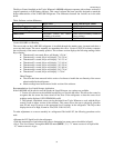
Indicates Open Sensor
1. Normally, this message is associated with a loose plug or connector. Check the connection at the foot of
the controller labeled SENSORS.
2. If the problem persists, the sensor assembly may need to be replaced. To determine this select: MENU,
LEVEL SENSING, TEST LEVEL SENSORS. An “L”, “G”, or “O” (open) will indicate individual
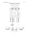
thermistor status. If you still suspect the controller, confirm the sensor integrity using an ohm meter. Refer
to Figure 9 Pin View Schematics.
• Thermocouple is not repairable. Replace from stock.
Temperature reading 10 to 20 degrees warm.
• Prepare an ice water slurry with crushed ice and tap water. Dip or pour LN2 into a styrofoam cup to
prepare an LN2 bath. Calibrate the controller. Select MENU, TEMPERATURE, CALIBRATE
TEMPERATURE. Follow the on-screen instructions. Hold the thermocouple in each bath until the
control completes its self-calibration.
• Make sure the thermocouple is clean and dry before and after each bath.
• Reposition the thermocouple at the elevation the customer wants to monitor or control.