


Page 15
INPUT CHECK AND ADJUSTMENT
1. Make sure all gas appliances are off except the furnace.
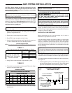
2. Clock the gas meter with the furnace operating (determine the
dial rating of the meter) for one revolution.
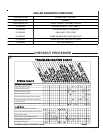
3. Match the “Sec” column in the gas flow (in cfh) Table 3 with the
time clocked.
4. Read the “Flow” column opposite the number of seconds
clocked.
5. Use the following factors if necessary.
For 1 Cu. Ft. Dial Gas Flow CFH =
Chart Flow Reading / 2
For 1/2 Cu Ft. Dial Gas Flow CFH =
Chart Flow Reading / 4
For 5 Cu. Ft. Dial Gas Flow CFH =
10X Chart Flow Reading / 4
6. Multiply the final figure by the heating value of the gas obtained
from the utility company and compare to the nameplate rating.
This must not exceed the nameplate rating.
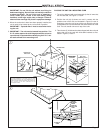
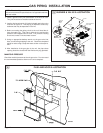
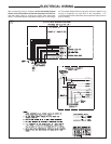
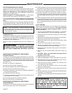
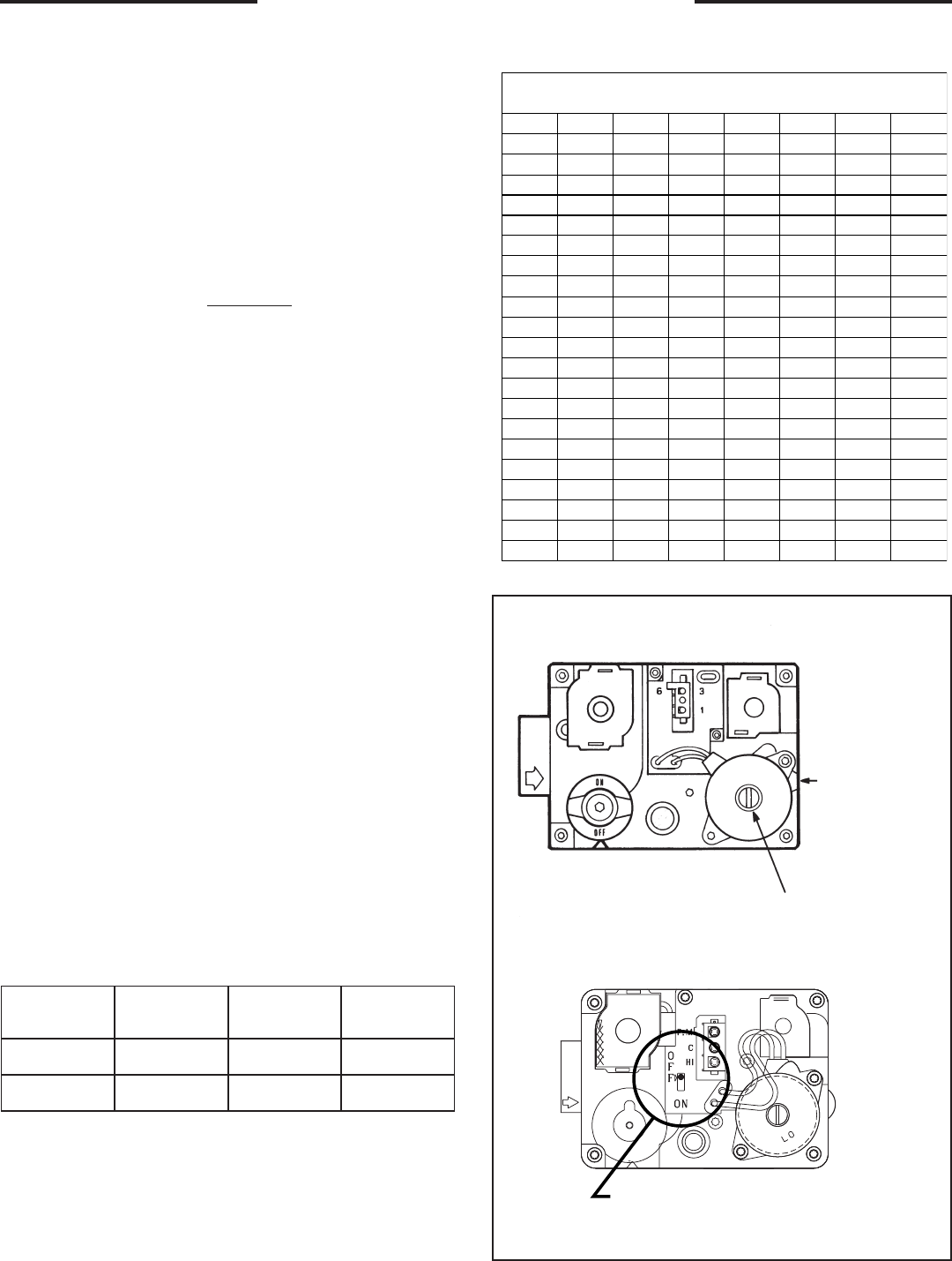
7. Changes can be made by adjusting the manifold pressure.
a. Attach a manifold pressure gauge.
b. Remove the slot screw on top of the gas valve for 1st stage
manifold pressure adjustment. Remove slot screw on outlet
side for 2nd stage adjustment (See Figure 17).
c. Turn the adjustment nut in to increase the gas flow rate, and
out to decrease the gas flow rate using a 3/32" hex wrench.
Note:
If Model YCZ036F1,3M is installed in a region where NOX must be
below 40 nanograms per input to 72,000 BTUH.
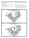
GAS PIPING INSTALLATION
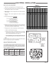
GAS FLOW IN CUBIC FEET PER HOUR
2 CUBIC FOOT DIAL
Sec. Flow Sec. Flow Sec. Flow Sec. Flow
8 900 29 248 50 144 82 88
9 800 30 240 51 141 84 86
10 720 31 232 52 138 86 84
11 655 32 225 53 136 88 82
12 600 33 218 54 133 90 80
13 555 34 212 55 131 92 78
14 514 35 206 56 129 94 76
15 480 36 200 57 126 96 75
16 450 37 195 58 124 98 73
17 424 38 189 59 122 100 72
18 400 39 185 60 120 104 69
19 379 40 180 62 116 108 67
20 360 41 176 64 112 112 64
21 343 42 172 66 109 116 62
22 327 43 167 68 106 120 60
23 313 44 164 70 103 124 58
24 300 45 160 72 100 128 56
25 288 46 157 74 97 132 54
26 277 47 153 76 95 136 53
27 267 48 150 78 92 140 51
28 257 49 147 80 90 144 50
TABLE 3
u
1st Stage (Lo)
Manifold
Pressure
Adjustment
2nd Stage (Hi)
Manifold
Pressure
Adjustment
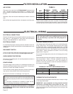
HIGH ALTITUDE INSTALLATION
Unit nameplate ratings are based on equipment operation from sea
level to 2000 feet elevation above sea level. If the unit installation
is from 2000 - 4500 feet elevation, it will be necessary to change
the burner orifices to the noted sizes, (ref. National Fuel Gas Code,
sec 8.1.2, Appendix F, Table F4).
SAG
EPYT
SSERP.NAM
).C.W.ni(
EZISECIFIRO
tf0002-0
EZISECIFIRO
tf0054-0002
LARUTAN3.3
24
*
34
ENAPORP0.014555
* DEPPIHSYROTCAF
Switch Toggles
"ON" or "OFF"