Page 20
o
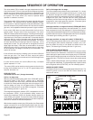
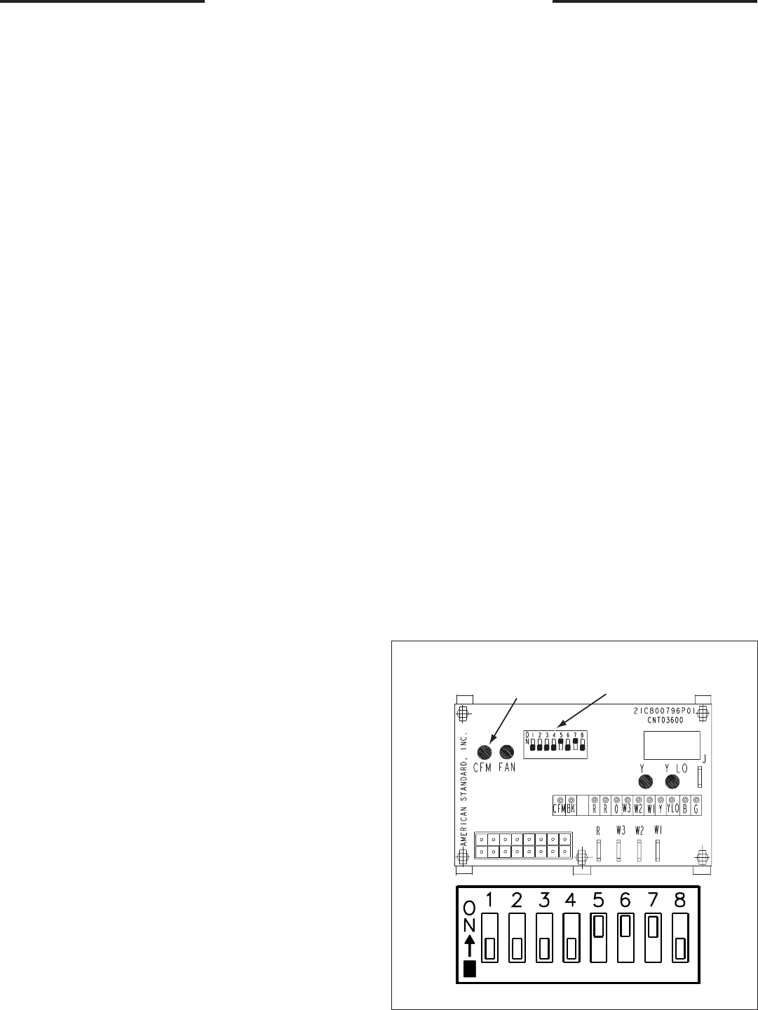
DIP SWITCHES (TYPICAL SETTINGS)
SEQUENCE OF OPERATION
ICM FAN CONTROL
The rollout switch (FS) is located in the gas compartment near the
inlet of the burners. This is a single use device designed to protect
against any form of flame rollout. If this device is opened the gas
valve is immediately de-energized and the control (IGN) will lockout
the system. The rollout switch (FS) must be replaced before
operation is allowed to continue.
The pressure switch (PS) is located in the upper right side of the gas
compartment. This automatic device assures adequate combus-
tion air pressure. If pressure against the induced draft blower outlet
becomes excessive, the pressure switch will react and shut off the
gas valve, until acceptable combustion pressure is again available.
If the control (IGN) does not sense flame within the first trial for
ignition period. The gas valve will be de-energized. The control
(IGN) will initiate a 60 seconds interpurge. Following the interpurge,
on the second trial the gas valve will be energized on second stage
(high heat input). If the flame is sensed within 10 seconds after the
second try and only a call for first stage exists, the gas valve will be
reduced to first stage. If the second try is not successful. The control
will start other 60 second interpurge. After the interpurge, a third
attempt will be tried. The gas valve will be energized on second
stage (high heat input). If the flame is sensed within 10 seconds
after the third try and only a call for first stage exists, the gas valve
will be reduced to first stage. If the third try is not successful. The
control will lock out.
If loss of flame occurs during a heating cycle, the control (IGN) will
close the gas valve. The control will than recycle the ignition
sequence, then if ignition is not achieved, it will shut off the gas valve
and lock out the system.
If control lock out occurs, the control (IGN) will retry a complete
ignition sequence in 1 hour.
The control (IGN) can be reset by removing power to the unit or by
turning the thermostat from “on” to “off" for approximately three
seconds, then back “on.”
COOLING CYCLE
Thermostat call for cool ( 2-stage thermostat)
Call for 1st stage only:
With the room thermostat system switch in the “COOLING” position
and the fan switch in the “AUTO” position, the Y1 thermostat
contacts closes to the micro board, (the board will wait 3 seconds
to check if the Y2 may also be calling) the micro will energize (CC1)
and the outdoor fan relay for low speed and the G thermostat
contact to G-IGN and to G1 on the ICMC is energized. (The status
light is flashing and the Y1 light is on.)
The energized compressor contactor (CC1) completes the circuit to
the compressor (CPR1), If the compressor safety controls are
closed, the compressor (CPR1) will operate with the outdoor fan
motor (ODM) on low speed. The indoor fan motor (IDM) will operate
on low speed. The thermostat will continue to cycle the compressor
and fans to maintain the desired temperature.
With the thermostat fan switch in the “ON” position, the G thermostat
contact is closed to G1 on the ICMC board and the indoor fan motor
(IDM) will continue to run on low speed regardless of compressor
and condenser fan operation.
Call for 2nd stage after 1st stage:
The Y2 thermostat contact closes to the control board. For 1 minute
both compressors are off, (all lights are flashing for 1 minute), than
the board will energize the (CC2) compressor contactor, and the
outdoor fan relay for high speed then the board (YCZ050 ONLY- will
energize the (CC1) and 1 second later the (CC2) compressor
contactors) and the indoor fan high to the Y on the ICMC board is
energized for indoor high speed fan operation. (The status light is
flashing and the Y1 and Y2 lights are on.)
2nd stage satisfied, 1st stage still called:(YCZ036,060F ONLY)
The Y2 thermostat contact opens to the control board. For 1 minute
both compressors are off, (the status and Y1 light are flashing for 1
minute), than the board will energize (CC1) low compressor contactor,
and the outdoor fan relay for low speed and indoor fan for low speed.
(The status light is flashing and the Y1 light is on.)
2nd stage satisfied, 1st stage still called:( YCZ050 ONLY)
The Y2 thermostat contact opens to the control board. The board
will de-energize (CC2) second compressor contactor, and ener-
gize the outdoor fan relay for low speed and indoor fan for low
speed. (The status light is flashing and the Y1 light is on.)
ICM FAN MOTOR ADJUSTMENTS
If the airflow needs to be increased or decreased, see the Indoor
Blower Performance Table below. Information on changing the dip
switch settings for speed control of the blower motor is in this table.
Blower speed changes are made on the ICM Fan Control mounted
in the control box. The ICM Fan Control controls the variable speed
motor.
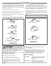
There is a bank of 8 dip switches, (See Figure below), located at the
lower right side of the board. The dip switches work in pairs to select
the cooling/heat airflow (CFM/TON), and Fan off-delay options.
INDOOR BLOWER TIMING
The ICM Fan Control controls the variable speed indoor blower. The
FAN-OFF period is set on the ICM Fan Control board by dip
switches #5 and #6.
CFM
SELECTION
LIGHT
DIP
SWITCHES


