


Page 9
INSTALLATION
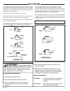
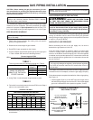
IMPORTANT: Do not lift the unit without test lifting for
balance and rigging. Do not lift the unit in windy conditions
or above personnel. Do not lift the unit by attaching a
clivus, hooks, pins, or bolts to the unit casing, casing
hardware, corner lugs, angles, tabs, or flanges. Failure to
observe these warnings may result in equipment damage.
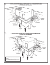
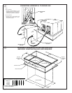
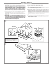
4. When the curb and air ducts have been properly installed, the
unit is ready to be hoisted to the roof and set in position.
IMPORTANT: “Spreader Bars” must be used when hoist-
ing the unit.
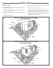
5. IMPORTANT: The unit must be lowered into position. The
P.V.C. rubber tape on the curb flange permits the unit to be
repositioned if required without destroying the P.V.C. rub-
ber seals affixed to the mounting curb.
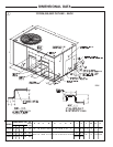
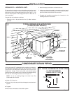
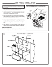
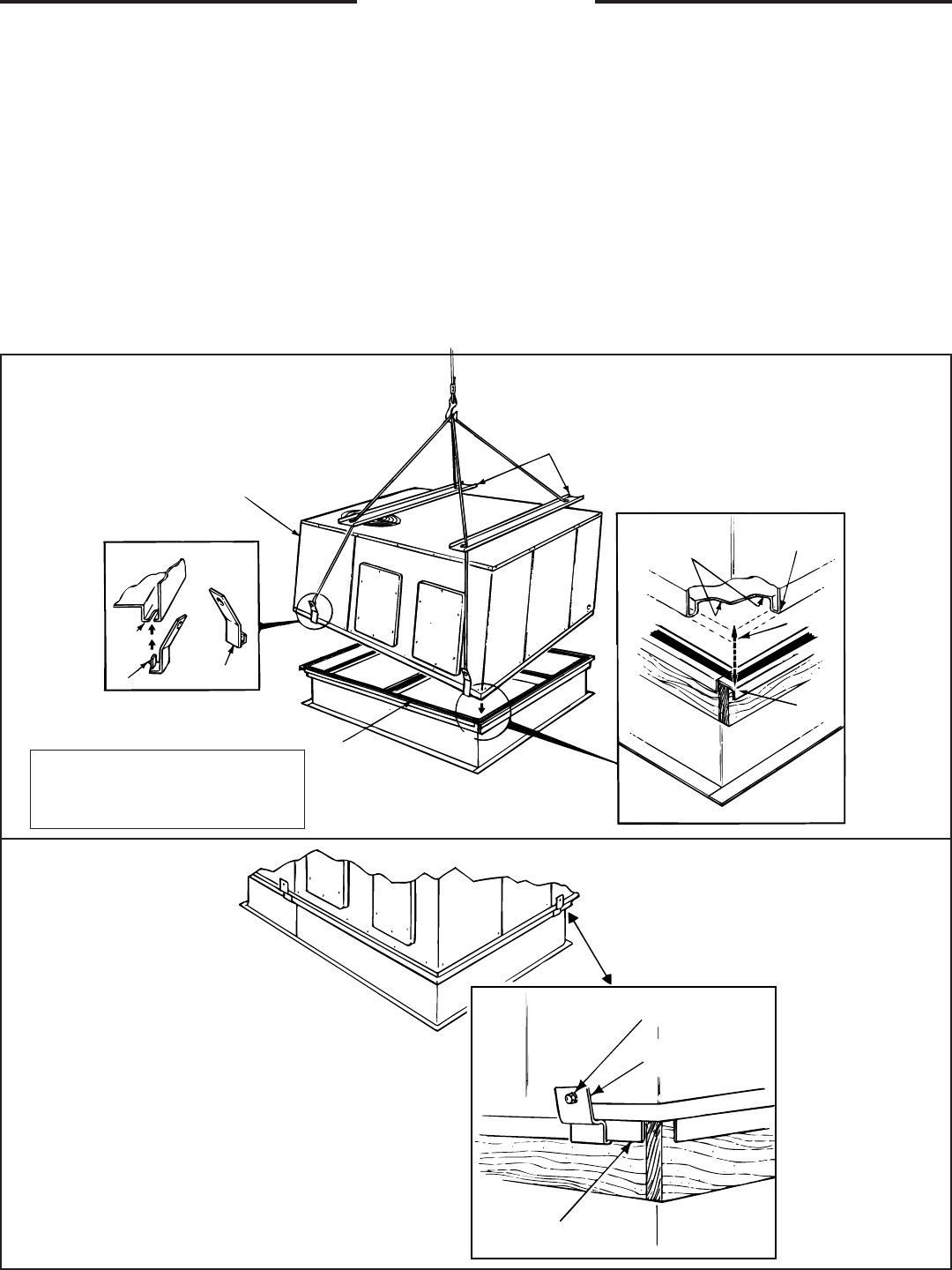
PLACING THE UNIT ON A MOUNTING CURB
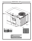
1. The unit is designed with a perimeter drip lip that is lower that
the unit base bar, see Figure 7, inset A.
2. Position the unit drip lip down over and in contact with the
outside corner of the curb, as illustrated in Figure 8, insert A.
Continue to lower the unit on top of the curb, with the unit drip
lip astraddle and in contact with both the end and side rail of the
curb. The unit should now rest on top of the curb.
3. Take the two (2) hold-down brackets shipped with the curb and
secure the unit to the curb with hold-down brackets as illus-
trated in Figure 8, insert A.
7
8
SPREADER BARS
OUTDOOR COIL
END OF UNIT
GASKET SEAL
BASE OF UNIT
REST ON TOP OF
CURB RAILS
DRIP LIP
DIMPLE
BAYLIFT002A
LIFTING LUGS
SEE DETAIL “A”
“B”
“A”
DRIP LIP ON
PERIMETER OF UNIT
UNIT CORNER
CURB CORNER
EXISTING
SHEET METAL
SCREW
HOLD-DOWN
BRACKET WITH
CURB
FLANGE OF
CURB
“A”
NOTE:
THE INNER PERIMETER OF THE DRIP LIP ON ALL UNITS
SHOULD BE FLUSH WITH THE OUTER PERIMETER OF THE
CURB ON THE TWO SIDES SHOWN HERE. SEE FIGURE 2 FOR
THE LOCATION OF THE UNIT OVERHANG ON THE
YCZ036-060F MODELS.