CG-PRC007-EN34
Standard Control Features
Human Interface (HI) Panel
The Human Interface (HI) Panel provides
a 2 line X 40 character clear English
language liquid crystal display and a 16
button keypad for monitoring, setting,
editing and controlling. The Human
Interface Panel is mounted in the unit’s
main control panel and is accessible
through a hatch built into the unit’s
control panel door.
The optional remote-mounted version of
the Human Interface panel has all the
functions of the unit-mounted HI, with
the exception of the Service Mode. To
use a Remote Human Interface (RHI), the
unit must be equipped with an optional
InterProcessor Communications Bridge
(IPCB). The RHI can be located up to
5,000 feet from the unit. A single RHI can
be used to monitor and control up to 4
chillers, each containing an IPCB.
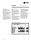
The Main Menu of the Human
Interface panel:
STATUS — used to monitor all
temperatures, pressures, set points,
input and output status. The CUSTOM
KEY will have four reports that can be
user defined. The report screens consist
of the data available in the main status
menu.
SET POINTS — used to edit all factory
preset default set points and assign set
point sources.
DIAGNOSTICS — used to review active
and historical lists of diagnostic
conditions. A total of 41 different
diagnostics can be read at the Human
Interface Panel. The last 20 diagnostics
can be held in an active history buffer log
at the Human Interface Panel.
SETUP — Control parameters, sensor
selections, set point source selections,
output definitions, and numerous other
points can be edited from this menu. All
points have factory preset values so
unnecessary editing is kept to a
minimum.
CONFIGURATION — Preset with the
proper configuration for the unit as it
ships from the factory, this information
would be edited only if certain features
were physically added or deleted from
the unit. For example, if a field supplied
Trane Communication Interface (TCI)
module was added to the unit in the
field, the unit configuration would need
to be edited to reflect that feature.
SERVICE — used to selectively control
outputs (for compressors, fans, etc.)
when servicing or troubleshooting the
unit. This menu is accessible only at the
unit-mounted Human Interface Panel.
STOP, AUTO — when the chiller is in the
stop mode, pressing the AUTO KEY will
cause the UCM to go into either the
Auto/Local or Auto/ICS mode, depending
on the set point source setting.
Chiller Capacity Control — The Unit
Control Module (UCM) will control
leaving solution temperature to a user
adjustable set point. The UCM monitors
the leaving solution temperature sensor
and determines how far away this
temperature is from the leaving solution
set point and how long it has been there.
The rate at which capacity stages are
added or subtracted is determined by a
control integrator algorithm. This
algorithm calculates a control integrator
value based upon the inputs from the
control response set point, the difference
between the leaving solution set point
and the leaving solution temperature,
the number of capacity steps, and the
design delta temperature. This function
can be user defined for comfort or
process control applications. The
following set points are integrated into
the capacity control algorithm:
Leaving Solution Set point (LSS) — The
LSS is adjustable from the factory as
standard within a range from 40-50°F.
Three other possible ranges can be
selected and ordered from the factory,
20-29, 30-39°, and 51-65°F. When these
options are selected, the unit hardware
changes to allow the unit to operate
under safe conditions.
Design Delta Temperature set point —-
the design delta T drop within the
evaporator is adjustable from 4-20 °F in
one degree increments. In addition, the
control response set point can affect the
speed of the UCM’s response to
changing cooling requirements. This
value can be set through the HI to allow
flexibility in maintaining precise control
conditions.
Chiller Freeze Protection — The
microprocessor will prevent the
evaporator fluid from freezing by
reducing chiller capacity, ultimately
shutting down all compressors and
sending a manually re-settable
diagnostic. The inputs for freeze
protection are the low leaving solution
temperature cutout and the leaving
solution temperature.
Evaporator Solution Flow Interlock —
The IntelliPak control requires an
external evaporator flow switch interlock.
An external field installed flow switch
must be wired into the unit terminal
strip. When an open condition is
detected for six (6) seconds or longer, the
compressors will shut down and after
five (5) minutes an automatic resettable
diagnostic alarm will be sent.
(20–60 Ton
Interface)Controls


