


-1-
TABLE OF CONTENTS
VI. Blast Chill Operation (cont’d)
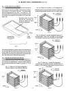
c-Grouping Foods To Form Batches Page 7
d-Maximum Load Per Batch Page 8
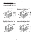
e-Pan Placement In Unit Page 8
f-Food Probe Placement Page 9
g-Example Batches For RBC50 Page 9
h-Example Batches For RBC100 Page 10
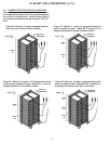
i-Example Batches For Roll-In/Roll-Thru Models Page 11
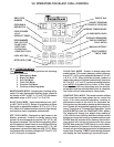
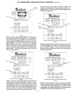
VII. Operating The Blast Chill Control
a-Operating Modes Page 12
b-Continuous Batching Page 13
c-Probe Temperatures Page 13
d-Lock Function Page 13
e-Unlock Function Page 13
f-Defrost Function Page 13
g-Printout Data Page 13
h-Resetting Date & Time Page 13
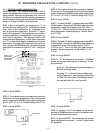
i-Programming A New Batch Page 13/14
j-Control Panel Configuration Page 15
k-Probe Temperature & Alarm Warnings Page 16
VIII. Understanding Printouts
a-Current Data Printout Page 16
b-Constant Chill Cycle - Batch Data Page 16
c-Blast Chill Cycle - Batch Data Page 17
d-72-Hour Data Log Page 18
e-Food Probe Failure Warnings Page 19
IX. Trouble Shooting Guide Page 20
X. Wiring Diagrams Page 21-24
XI. Warranty Information Page 25
XII. Parts List Page 26
XIII. Index Page 26
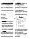
I. The Serial Tag Page 1
II. Receipt Inspection Page 2
III. Installation
a-Location Page 2
b-Packaging Page 2
c-Wiring Diagram Page 2
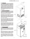
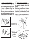
d-Installing Legs or Casters Page 2
e-Cord & Plug Page 3
f-Electrical Requirements Page 3
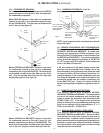
g-Proper Clearances Page 3
h-Condensate Removal Page 4
i-Remote Unit BTU Requirements Page 4
j-Remote Unit Cut-Out Settings Page 4
k. Sealing Roll-In/Roll-Thru Units Page 4
l. Installing RBC50 Control Panel Page 5
m. Attaching RBC400 Units Together Page 5
IV. Care & Maintenance
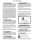
a-Cleaning The Condenser Page 6
b-Cleaning The Exterior Page 6
c-Cleaning The Interior Page 6
d-Installing Printer Paper Page 6
V. Other
a-Service Agency Check & Start-Up Page 6
b-On-Site Blast Chill Training Page 6
c-Service Information Page 6/7
d-Demonstrations Page 7
e-Blast Chill Video Page 7
f-Blast Chill Data Communications Kit Page 7
VI. Blast Chill Operation
a-Loading Food Into Pans Page 7
b-Covering Foods Page 7
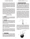
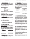
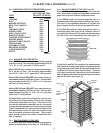
The serial tag is a permanently affixed sticker on
which is recorded vital electrical and refrigeration data
about your Traulsen product, as well as the model
and serial number. This tag is located inside the
door on the right interior wall of the cabinet.
I. THE SERIAL TAG
FORT WORTH, TX.
SERIAL MODEL
VOLTS Hz PH
TOTAL CURRENT AMPS
MINIMUM CIRCUIT AMPS
MAXIMUM OVERCURRENT PROTECTION AMPS
LIGHTS WATTS
HEATERS AMPS
REFRIGERANT TYPE OZ
DESIGN PRESSURE HIGH LOW
REFRIGERANT TYPE OZ
DESIGN PRESSURE HIGH LOW
370-60294-00 REV (A)
R
R
AW-03118
READING THE SERIAL TAG
• Serial = The permanent ID# of your Traulsen
• Model = The model # of your Traulsen
• Volts = Voltage
• Hz = Cycle
• PH = Phase
• Total Current = Maximum amp draw
• Minimum Circuit = Minimum circuit ampacity
• Lights = Light wattage
• Heaters
• Refrigerant = Refrigerant type used
• Design Pressure = High & low side operating
pressures and refrigerant charge
• Agency Labels = Designates agency listings