


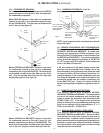
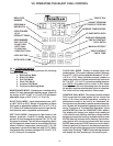
III. INSTALLATION (continued)
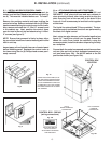
III. m - ATTACHING RBC400 UNITS TOGETHER:
This section applies only to models RBC400 and
RBC400RT. First, place the front and rear cabinets in
close proximity to each other being careful to align the
drain from the front of the rear unit to the drain of the
front unit. It will be necessary to level both units together
at this time.
The liquid line solenoid and TXV are provided. The tem-
perature control and defrost functions are performed by
the blast chill digital control.
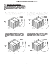
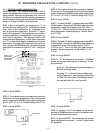
Next, using two pipe clamps, pull the units together(see
figure 10). Install the covers over the gap formed be-
tween the units From inside the cabinets, using the
screws provided, install the breaker strips using the strip
as a template.
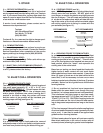
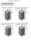
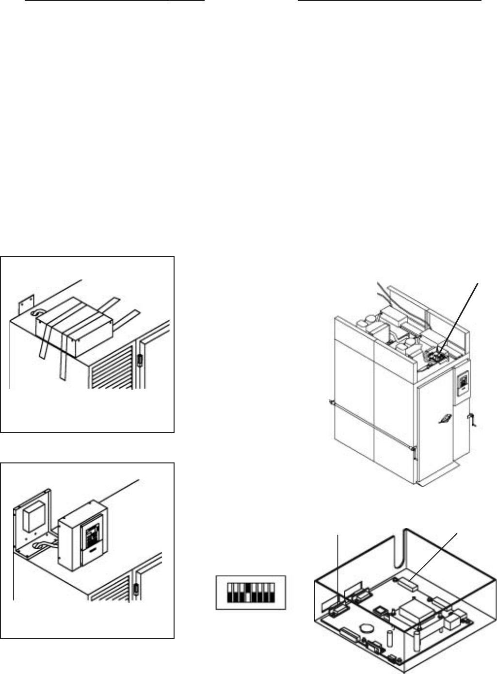
Connect both the probe harness and control harness from
unit two (the rear unit) to their dedicated connectors on
unit one (see figure 10a). Set #4 DIP switch to the ON
position as shown (see figure 10b).
-5-
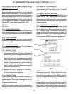
Fig. 8
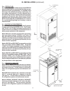
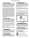
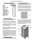
III. l - INSTALLING RBC50 CONTROL PANEL:
Model RBC50 is shipped with the control panel de-
tached, and laid flat, taped to the cabinet top (see fig-
ure 8). This must be installed before use. To install:
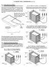
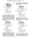
Remove the packing material and tape holding the
control to the top. Remove and retain the six (6) Phillips
head screws attaching the control cover to the frame.
Also, remove and retain the 14”- 20x1/2” screws found
in the cabinet top. Next, position the control frame
over the hole in the unit top and attach using 1/4-20x1/
2” screws (see figure 9).
NOTE: Ensure that grommet is firmly in place, align-
ing round hole in bottom of control housing with round
hole in unit top.
Inspect paper roll and spindle from rear of control panel
before installing panel. Reattach the control cover to
the frame using the six (6) Phillips head screws previ-
ously removed.
Fig. 9
Fig. 10
USING TWO PIPE CLAMPS, PULL
THE TWO UNITS TOGETHER AND
USING THE SCREWS PROVIDED.
ALIGN THE BREAKER STRIPS AS
A TEMPLATE FOR THE SCREW
PATTERN INSIDE AND OUTSIDE
THE CABINET.
CONTROL BOX
LOCATION
UNIT 2
PROBE HARNESS
CONNECTOR
UNIT 2 CONTROL
HARNESS
CONNECTOR
CONTROL BOX - RBC400
(wiring connections)
Fig. 10a
SET #4 DIP SWITCH
TO ON POSITION
AS SHOWN FOR RBC400
AND RBC400RT.
Fig. 10b