


-9-
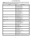
X. SERVICE PROCEDURES & ADJUSTMENTS (cont’d)
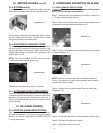
X. d-EVACUATING SYSTEM(cont’d):
1) Access the refrigeration system as outlined under “SYSTEM
ACCESS.”
2) Connect low (blue) side of gauge manifold to schrader valve
on compressor process line and high (red) side of gauge manifold
to schrader valve on lter/drier process line.
3) Connect center line of gauge manifold to vacuum pump.
4) Turn vacuum pump on and open both sides of gauge mani-
fold.
5) Pull a vacuum to 200 microns.
6) Break the vacuum with 3 psig of dry nitrogen.
7) Repeat steps 5 and 6.
8) Pull vacuum to 200 microns.
9) Charge system and check for proper operation.
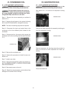
X. e-CHARGING SYSTEM:
Disconnect the electrical power to the machine
at the main circuit box. Place a tag on the circuit box indicat-
ing the circuit is being serviced.
This procedure requires the use of refrigerants,
be certain the work area is well ventilated. Safety goggles
and gloves shall be worn since refrigerants may cause burns
to the skin.
1) Access the refrigeration system.
2) Attach gauge manifold set to system, low side to process
tube on the compressor and the high side to the process tube
on the drier.
NOTE: See “SYSTEM ACCESS.”
3) Be sure the system is properly leak checked and evacuated
before charging as outlined under “LEAK CHECK” and “EVACU-
ATING SYSTEM.”
4) Make certain both valves are closed on the gauge manifold.
Open the valve on the bottle. Bleed charging hose at the manifold
gauge to remove air.
NOTE: Initially charge system through high side to prevent liquid
refrigerant from reaching compressor.
5) Open the high side gauge valve (red). Allow refrigerant to ow
into the system until the nameplate charge is reached or until the
high side will not accept any more refrigerant. At this point, shut
the gauge and bottle valves.
6) Reconnect power to the unit and check for proper operation
and high pressure leaks.
X. e-CHARGING SYSTEM (cont’d):
7) Add the remaining amount of refrigeration charge
through the low side with the compressor running.
8) Check for proper operation and leaks.
9) Disconnect power to the unit and replace any covers
removed.
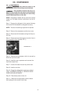
X. f-SYSTEM CLEAN UP/INTRODUCTION:
When a compressor burn-out or moisture inltration
is encountered, the service person must make the de-
termination as to the degree of system contamination.
Normally a compressor burn-out will t into one of three
categories:
• CONTAINED - compressor oil not acidic, no oil dis
coloration.
• CONTAMINATED COMPRESSOR - oil acidic,
discoloration of oil, contamination limited to
compressor.
• MASSIVE CONTAMINATION - contaminated oil
and/or refrigerant pumped through system.
CONTAINED
1) Replacement of liquid line drier.
2) Install suction lter drier for clean up and then remove
it when service is complete. Usually within 48-hours.
3) Replacement of compressor.
4) Evacuation (to 200 microns).
5) Charge by weight.
CONTAMINATED COMPRESSOR
The “contaminated compressor” requires the same pro-
cedure as the “contained” burn-out. Plus, the system
must be ushed with nitrogen after the compressor and
drier has been removed.
Certain procedures in this section require electrical test or measurements while power is applied to the
machine. Excercise extreme caution at all times. If test points are not easily accessible, disconnect power, attach
test equipment and reapply power to test.