


-4-
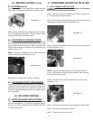
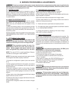
III. a-SYSTEM(cont’d):
To gain full access to the refrigeration system from the
side, remove the side cover by removing the screws.
When nished, place the louver assembly back into posi-
tion and replace the side panel. Secure these in place
using the previously removed screws.
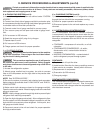
III. b-EVAPORATOR HOUSING COVER:
If the unit is supplied with a marine work top, rst remove
the work top by removing the mounting screws on the
left and right side of the work top. Next, remove the #3
Phillips head screws from the top of the evaporator and
cabinet space cover.
NOTE: The cover is sealed with RTV which may need
to be scored before removing the cover.
Reverse the procedure when done, to reinstall.
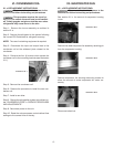
III. c-ACCESSING START COMPONENTS:
The start components are mounted on the compressor.
To access the start components, rst remove the louver
assembly and side panel as instructed in section III. a.
The start components are mounted on the back side of
the compressor.
IV. RE-HINGE DOOR(S)
IV. a-DOOR RE-HINGE INSTRUCTIONS:
Your Traulsen Full Size Undercounter model door(s)
are eld re-hingeable. If re-hinging is required, please
contact our Service Department at 800-825-8220 for
re-hinge instructions.
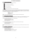
Illlustration III. 2
III. SERVICE ACCESS (cont’d)
Illustration III. 1
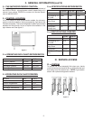
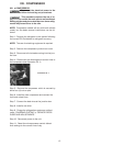
V. CONDENSER FAN MOTOR OR BLADE
V. a-REPLACEMENT INSTRUCTIONS:
Disconnect the electrical power to the machine
and follow lockout/tag out procedures.
Step 1: Remove the louver assembly as outlined in section III.
a. To gain access through left side.
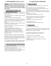
Step 2: Remove the screws holding the fan motor bracket to the
compressor mounting base (see Illustration V.1).
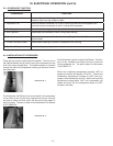
Step 3: Remove the blade from the motor shaft by removing the
nut (see Illustration V. 2).
NOTE: Install the concave side of the fan blade toward the
motor. If the blade is all that is being replaced, stop here and
reverse procedure to install.
Step 4: Remove the mounting bracket from the motor (see
Illustration V. 3).
Step 5: Disconnect lead wires at the compressor junction box.
Step 6: Reverse the procedure to install.
Step 7: Reconnect power to the unit.
Illustration V. 1
Illustration V. 2
Illustration V. 3