


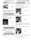
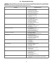

COMPONENT FUNCTION
1. Compressor Pumps refrigerant thru refrigeration system components and compresses the low
pressure vapor into high pressure vapor.
2. Evaporator Fan Draws air across condenser coil to aid in removing heat from the refrigerant and
moves air across compressor to aid in cooling the compressor.
3. Start Capacitor Stores electrical charge which helps start the compressor motor.
4. Run Capacitor Helps keep the compressor motor running after starting.
5. Microprocessor Control Performs the functions of the 1) defrost timer, 2) high limit switch, 3) thermometer and
4) thermostat.
6. Drawer Perimeter Heater Heats drawer opening to prevent condensation from forming.
7. Contactor Relay Controls voltage to compressor motors.
-11-
XI. ELECTRICAL OPERATION (cont’d)
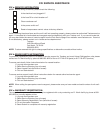
XI. c-COMPONENT FUNCTION:
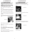
There are two sensors used inside the cabinet. The rst one is
the Cabinet Sensor that is used to cycle the compressor on and
off at the correct temperature. The cabinet sensor is mounted
through the wall of the evaporator housing on the return side of
the evaporator.
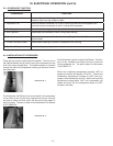
The Evaporator Coil Sensor is to be mounted in the evaporator,
in the center of the coil and fully inserted into the coil until only
the wire is visible and then pinch the ns around the cable to
hold it in place. The part number for the Evaporator Coil Sensor
is 337-60406-02.
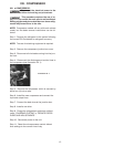
The third sensor used is a Liquid Line Sensor. This sen-
sor is to be installed on the liquid line as it comes out
of the condenser coil. The part number for this sensor
is 337-60407-01.
When the condensing temperature reaches 140°F or
greater the control will display “CLN-FIL.” Should the
condensing temperature increase to 160°F the com-
pressor will automatically shut off. When the liquid line
temperature drops below 140°F the compressor will
restart and when the line temperature drops to 120°F
the alarm will reset.
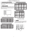
XI. d-INSTALLATION OF THE SENSORS:
Illustration XI. 1
Illustration XI. 2