


-8-
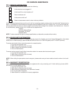
X. SERVICE PROCEDURES & ADJUSTMENTS
Certain procedures in this section require electrical test or measurements while power is applied to the
machine. Excercise extreme caution at all times. If test points are not easily accessible, disconnect power, attach
test equipment and reapply power to test.
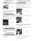
X. a-SYSTEM ACCESS:
All external indicators should be checked as part of
system diagnosis before determining the refrigerant
pressures. Improper access may expose the refrigerant
to contaminates and non-condensables which will result
in system failure.
X. b-SWEAT-ON PIERCING VALVES:
NOTE: Sweat-on piercing valves are used for system
diagnostics, but may be left on after service is com-
plete. They may be installed while the system is fully
charged.
1) Place one piercing valve on the compressor process
tube and one on the liquid line process tube. Follow the
installation instructions provided by the manufacturer of
the piercing valve.
2) When complete, follow the guidelines as outlined under
“REFRIGERATION LEAK CHECK” and “EVACUATING
SYSTEM.”
X. c-REFRIGERANT LEAK CHECK:
Disconnect the electrical power to the
machine at the main circuit box. Place a tag on the
circuit box indicating the circuit is being serviced.
This procedure requires the use of re-
frigerants, be certain the work area is well ven-
tilated. Safety goggles and gloves shall be worn
since refrigerants may cause burns to the skin.
NOTE: The use of R-22 in small quantities is Recom-
mended as a trace gas for leak detection.
NOTE: This leak check procedure is to be used only after
the refrigerant has been properly reclaimed.
1) Access the refrigeration system (note: see section
III. a).
2) Attach gauge manifold set to the system, low side to
process tube on the compressor and the high side to
the process tube.
3) Connect refrigerant bottle to the center of gauge
manifold and open the valve on the bottle. Bleed charg-
ing hose at the manifold gauge to remove air from the
system.
4) Open valve on low side of gauge manifold and charge
system with one ounce of R-22.
5) Close low side valve on gauge manifold and the valve
on the refrigerant bottle.
6) Disconnect refrigerant bottle and connect nitrogen
bottle.
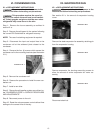
X. c-REFRIGERANT LEAK CHECK (cont’d):
NOTE: The use of a nitrogen regulator is required.
7) Set output valve on nitrogen valve to 120 psi.
8) Open nitrogen bottle valve and low side gauge manifold valve.
Allow pressure to equalize.
9) Shut off both valves and disconnect nitrogen bottle.
10) Use a leak detector or a thick soapy solution and check for
leaks at all tubing connections.
A - If leaks are found, repair leaks and repeat process.
B - If no leaks are found, evacuate system as outlined in section
“X. d - EVACUATING SYSTEM”).
11) Charge the system by weighing in the exact charge
and check for proper operation.
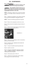
X. d-EVACUATING SYSTEM:
Introduction - Refrigeration reclaiming equipment is required. Our
goal in system evacuation is to remove all the non-condensables
possible. No evacuation method will remove 100% of the mois-
ture and air from within the refrigeration circuit. Because of this,
guidelines and methods must be developed and adhered to
ensuring only harmless amounts of contaminants remain in the
system.
GUIDELINES
Do not pressurize system above 150 PSIG, prior
to evacuation or during leak test procedures.
• Use only a two stage vacuum pump (2 CFM or
greater) and electronic micron.
• Evacuate from high and low sides of the system.
• No chemical additive or alcohols are to be used to
“dry up” a system.
• Blow down of system with DRY NITROGEN prior to
evacuation is acceptable and many times desirable.
See “System Clean-Up.” See page 9.
• Evacuate to 200 microns.
PROCEDURE
Disconnect the electrical power to the machine
at the main circuit box. Place a tag on the circuit box indicat-
ing the circuit is being serviced.
This procedure requires the use of refrigerants,
be certain the work area is well ventilated. Safety goggles
and gloves shall be worn since refrigerants may cause burns
to the skin.