V. c - REPLACING THE GASKETS:
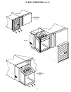
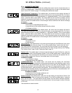
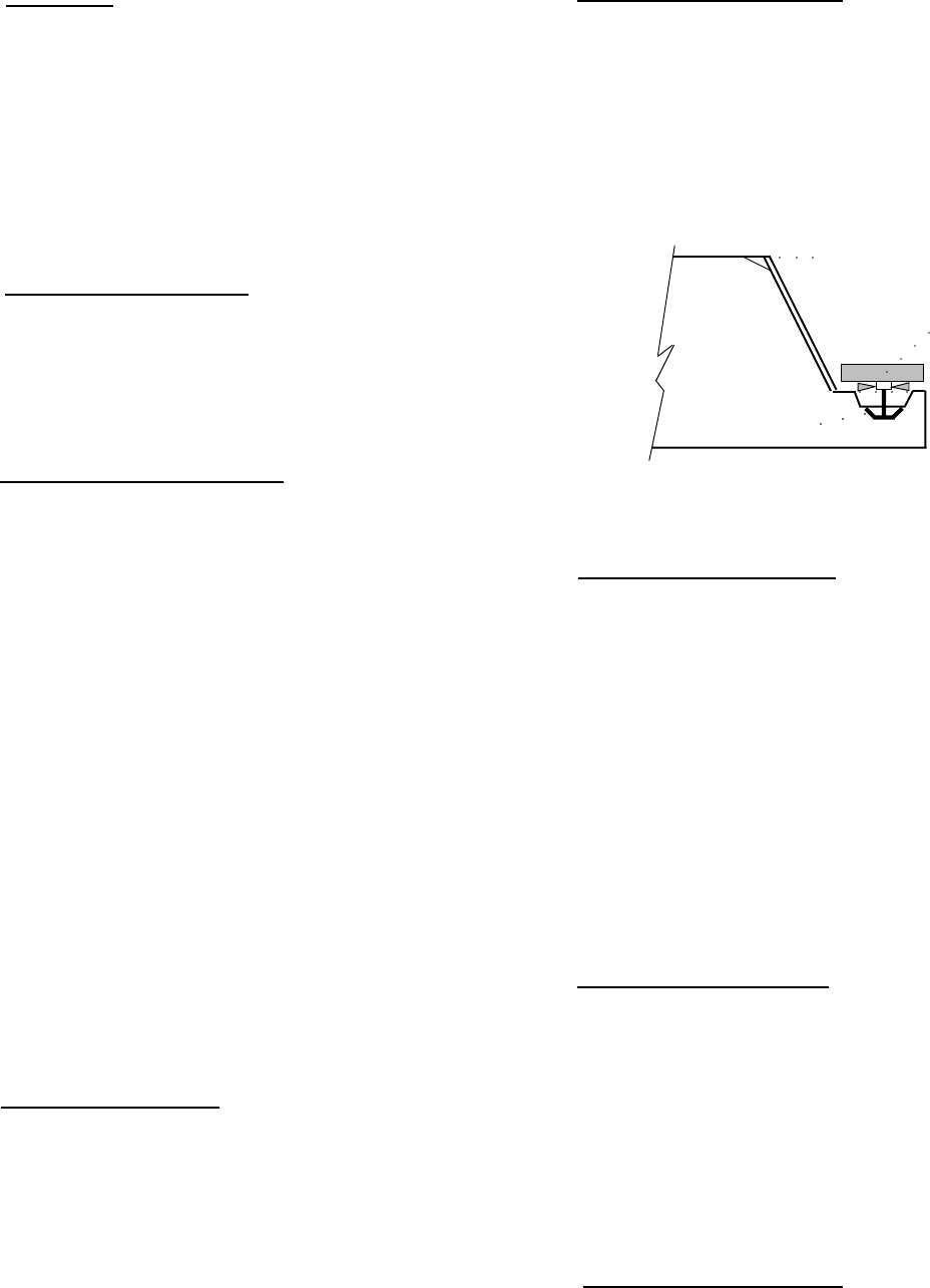
To remove the gasket to be replaced, grasp it firmly by
one corner and pull it out. Before attempting to install
a new gasket, both the unit and the gasket itself must
be at room temperature. Insert the four corners first
by using a rubber mallet (or hammer with a block of
wood). After the corners are properly inserted, work
your way towards the center from both ends by gently
hitting with a mallet until the gasket is completely
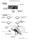
seated in place (see figure 5 for proper gasket place-
ment).
NOTE: The gasket may appear too large, but if it is
installed as indicated above it will slip into place.
V. d -
CLEANING THE EXTERIOR:
Exterior stainless steel should be cleaned with warm
water, mild soap and a soft cloth. Apply with a damp-
ened cloth and wipe in the direction of the metal grain.
Avoid the use of strong detergents and gritty, abra-
sive cleaners as they may tend to mar and scratch the
surface. Do NOT use cleansers containing chlorine,
this may promote corrosion of the stainless steel.
Care should also be taken to avoid splashing the unit
with water, containing chlorinated cleansers, when
mopping the floor around the unit.
For stubborn odor spills, use baking soda and water
(mixed to a 1 TBSP baking soda to 1 pint water ratio).
V. e - CLEANING THE INTERIOR:
For cleaning both stainless steel and anodized alumi-
num interiors, the use of baking soda as described in
section “V. d” is recommended. Use on breaker strips
as well as door gaskets. All interior fittings are re-
movable without tools to facilitate cleaning.
WARNING: DISCONNECT ELECTRICAL POWER
SUPPLY BEFORE CLEANING ANY PARTS OF THE
UNIT.
VI. MISC. OPERATIONS
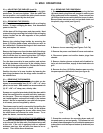
VI. a - ADJUSTING THE SHELVES:
For shelves mounted on pins, first select the desired
location and remove the white plastic covers in the
interior back and sides by rotating them counter-clock-
wise. Remove the shelf pins by rotating them counter-
clockwise. Install the pins in the desired location by
-4-
IV. b - FREEZERS (cont’d):
trols function upon termination of a defrost cycle is
two-fold. First, to prevent blowing warm air into the
food storage area. Second, to prevent any conden-
sation on the defrost coil from being blown into the
food storage area.
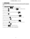
The INTELA-TRAUL control is set from the factory to
terminate defrost at 20 minutes in the event of a sen-
sor failure. This setting should never be tampered
with, without first consulting the factory.
IV. c - CONDENSATE REMOVAL:
Both refrigerator and freezer units are supplied with
an electric condensate evaporator for condensate re-
moval.
V. CARE & MAINTENANCE
V. a - CLEANING THE CONDENSER:
The most important thing you can do to insure a long,
reliable service life for your Traulsen is to regularly
clean the condenser coil.
The condensing unit requires regularly scheduled
cleaning to keep the finned condenser clean of lint
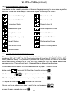
and dust accummulation. The INTELA-TRAUL con-
trol will notify you through a “CLN-FIL” message when
cleaning is necessary (see page 7). Keeping the con-
denser clean allows the cabinet to operate more effi-
ciently and use less energy.
To clean the condenser, first disconnect electrical
power to the cabinet and remove the front louver as-
sembly. To remove this, follow the directions in sec-
tion VI. d - Step #1. Once the screws are removed, the
panel can be removed allowing full access to the
powerpack. Vacuum or brush any dirt, lint or dust
from the finned condenser coil, the compressor and
other cooling system parts. If significant dirt is clog-
ging the condenser fins, use compressed air to blow
this clear.
Replace louver assembly, screws and caps.
V. b - HINGE REPLACEMENT:
Both the door and hinge can be easily removed from
the cabinet. To remove the door, remove the plug at
the bottom of the top hinge. Inside the hinge there is
a small screw which secures the door in place. Re-
move this with a flat head screwdriver and the door
can then be lifted off the hinge. To remove the door
half of the hinge from the door, lift off the hinge cover
and then remove the three Phillips head screws which
secure the hinge in place on the door. To remove the
cabinet half of the hinge, remove the three Phillips
head screws which hold it in place. To reassemble
the hinge reverse the previous procedure.
IV. OPERATION (continued) V. CARE & MAINTENANCE
Fig. 5
Inside Door Panel
Gasket Assembly
Vertical Gasket
Retainer


