


13
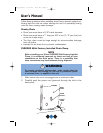
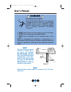
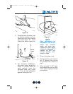
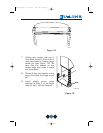
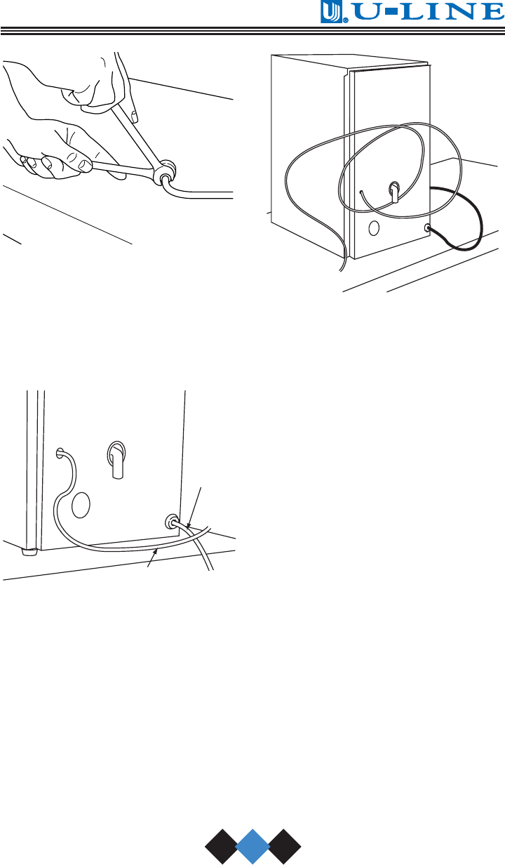
Figure 5
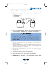
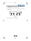
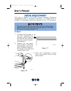
2. Carefully bend the water sup-
ply line into position and con-
nect the line to the solenoid
valve (see Figure 6). Avoid
kinking the water supply line.
Figure 6
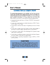
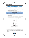
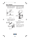
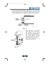
3. For recessed installations,
allow extra water supply line
length to provide slack for
easy removal from the
recessed area (see Figure
7). This will also safeguard
against kinking the line.
Figure 7
NOTE
After completing the
installation, turn on the
water and recheck
water and drain con-
nection for leaks. Apply
additional tightening if
needed. Do NOT use
thread sealing com-
pound or tape.
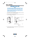
4. Plug in the power cord.
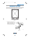
5. Gently push the unit into posi-
tion. If desired the unit may
be recessed into cabinet or
wall.
6. Allow at least 1-1/2" clear-
ance behind the unit for elec-
trical, water supply and drain
connections.
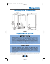
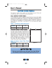
UL200
UL201
POWER
CORD
WATER LINE
UL134
Body_UM.qxd 12/17/04 9:16 AM Page 13