


NOTE
After completing the installation, turn on the water and
recheck water and drain connection for leaks. Apply addi-
tional tightening if needed. Do NOT use thread sealing com-
pound or tape.
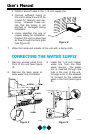
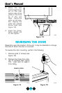
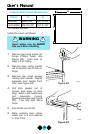
NOTE
Route the water supply line through the clip on the sidewall
of the unit in such a way as to prevent the line from com-
ing in contact with any internal components other than the
solenoid valve (see Figure 5). Normal operation creates
some vibration. A water supply line contacting an internal
component or cabinet wall may cause excessive noise dur-
ing operation or damage to the line.
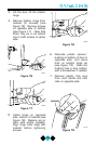
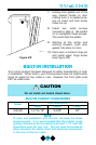
7. Re-install back panel and grommet.
8. Install access panel.
9. Install the grille. See GRILLE INSTALLATION.
10. Plug in the power cord.
11. Gently push the unit into position. If desired the unit may be
recessed into cabinet or wall.
12. Allow at least 1-1/2 inches clearance behind the unit for electri-
cal, water supply and drain connections.
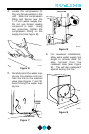
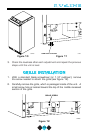
LEVELING THE UNIT
NOTE
It is extremely important that the unit is level. If it is not
level, the ice mold will not fill evenly. This can cause a reduc-
tion in ice rate, uneven sized cubes or water spilling into the
storage area which will cause the ice in the bin to melt pre-
maturely. Remember that floors near drains have a ten-
dency to slope towards the drain.
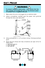
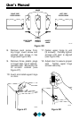
1. Use a level to check the levelness of the ice maker from front to
back and from side to side (see Figure 10).
2. If the ice maker is not level, adjust the feet on the corners of the
unit as necessary (see Figure 11).
12
User’s Manual