


NOTE
Use care not to bend light switch bracket (where installed),
located on door bottom when installing door insert. Do not
set door on bottom edge when pushing insert into place.
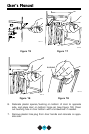
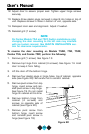
6. Slide custom door panel insert into 1/4 inch channel in door front.
7. Holding door gasket out of the way, replace handle on door mak-
ing sure it is seated properly on insert and that screw holes line
up.
8. Install two small screws removed in step 3.
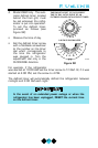
9 Starting at the center and working outward, push door gasket into
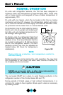
place on door.
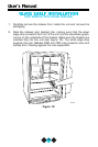
10. Place door on bottom hinge pin and install upper hinge screw (see
Figure 25).
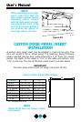
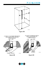
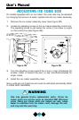
BUILT-IN INSTALLATION
Your U-Line product has been designed for either free-standing or built-
in installation. When built-in, your U-Line product does not require addi-
tional air space for top, sides, or rear. However, the front grill must
NOT be obstructed.
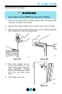
NOTE
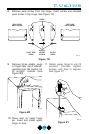
Combo Models 29A, 29FF, 75A, and 75FF require addi-
tional clearance when the door opens from the right (see
Figures 29 and 30). This additional clearance allows for the
ice bucket to be removed from the unit.
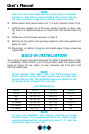
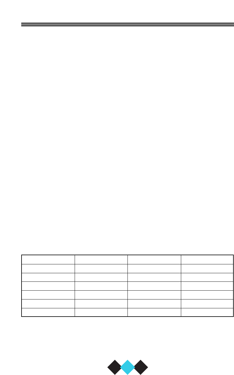
Unit Dimensions
Model Width Height Depth
SP18 13-15/16" 18-1/2" 25-1/4"
95 13-13/16" 24-3/4" 17"
98 14-13/16" 27-3/8" 20"
15 Series 14-15/16" 34 - 35" 23-3/4"
29 Series 20-13/16" 28-1/2" 24"
75 Series 23-7/8" 34 - 35" 24"
NOTE
To ease unit installation and removal, increase the above
measurements. It is recommended that the cabinet rough
opening dimensions be increased by at least 1/4" over the
dimensions given for your unit.
18
User’s Manual