21
3
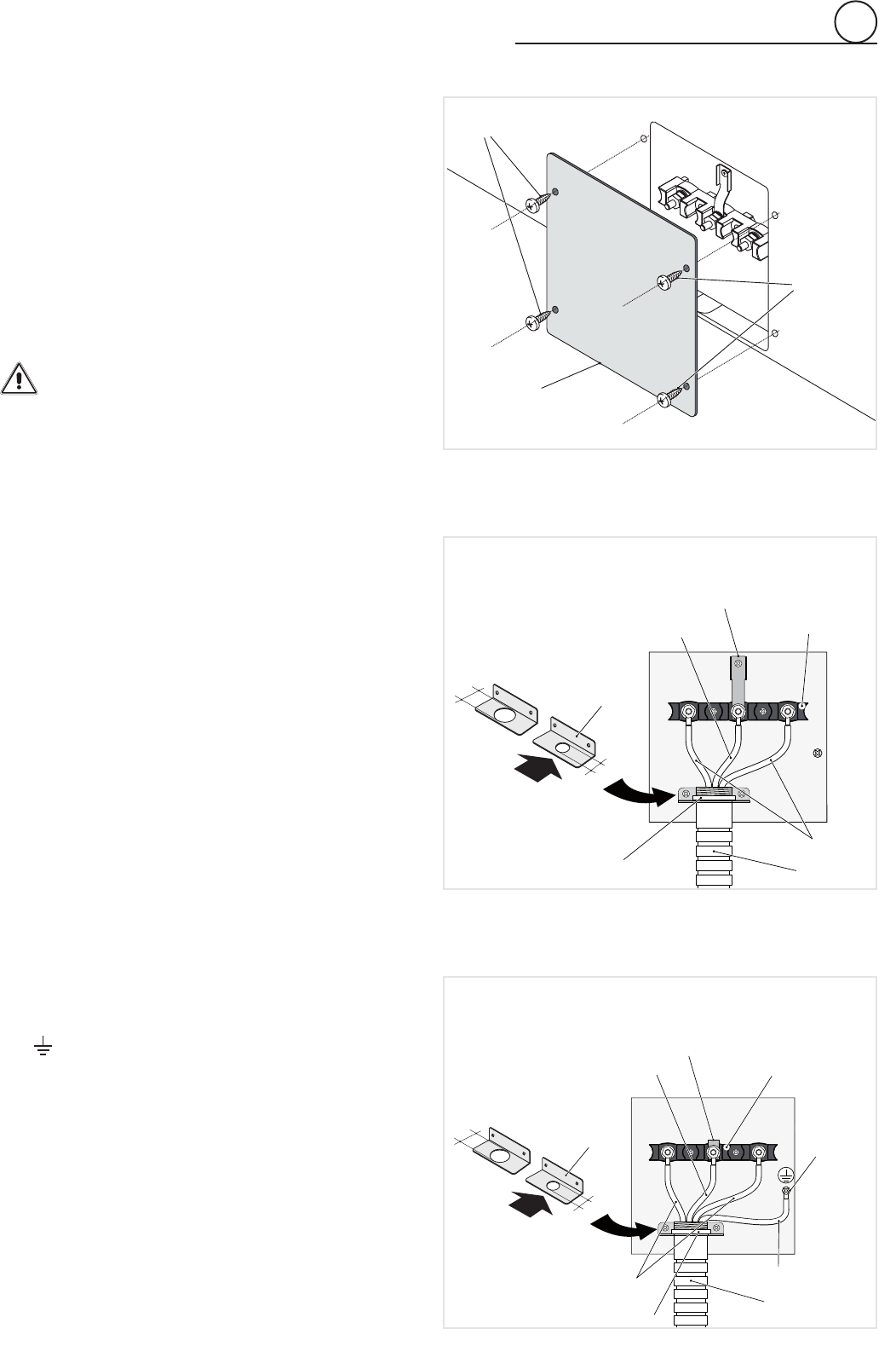
3-Wire Conduit Installation (SeeFigure3.5)
1. RemovetheTerminal Block Access Plateonthebackofthe
rangebyunscrewingthe4xingScrews(Figure3.4).
2. CheckthecorrectpositioningoftheConduit Bracketasper
gure3.5.
3. Feed1/2”(1.3cm)tradesizeConduitthroughtheholeinthe
Conduit BracketandsecuretotheConduit Bracketwitha
Conduit Clamp.
4. Plugtheterminalholesofconductors.
TheNeutral or Ground Wiremustbeconnectedtotheneutral
terminallocatedinthecenterofTerminal Block.
ThePower Wiresmustbeconnectedtotheoutsideterminals.
5. Plugwashersandtightennutssecurely.
DonotremoveGround strap.
6. ReassembletheTerminal Block Access Plateonthebackof
therangebyscrewingthe4xingScrews(Figure3.4).
4-Wire Conduit Installation (SeeFigure3.6)
1. RemovetheTerminal Block Access Plateonthebackofthe
rangebyunscrewingthe4xingScrews(Figure3.4).
2. CheckthecorrectpositioningoftheConduit Bracketasper
gure3.6.
3. Feed1/2”(1.3cm)tradesizeConduitthroughtheholeinthe
Conduit BracketandsecuretotheConduit Bracketwitha
Conduit Clamp.
4. Removethe3wireterminalnutsandwashersfromtheTermi-
nal Block.
5. RemovetheGround Strapfromtheframeofrangeandtermi-
nalbyremovingitsscrewandcuttingitasshowninFigure3.6.
6. Plugtheterminalholesofconductors.
TheNeutral Wiremustbeconnectedtotheneutralterminal
locatedinthecenterofTerminal Block;thePower Wiresmust
beconnectedtotheoutsideterminals;theGround Wiremust
beattachedtotheframeofrangebyusingthe(Ground)identi-
ed
Grounding Screw.
7. Plugwashersandtightennutssecurely.
8. ReassembletheTerminal Block Access Plateonthebackof
therangebyscrewingthe4xingScrews(Figure3.4).
Terminal Block
Ground strap
Neutral Wire
Power Wires
Conduit
Conduit Clamp
B
Power Cord
Bracket
A: D=1” 9/64 (29 mm)
B: D=7/8” (22.5 mm)
A
Terminal Block
Cut Ground Strap
Neutral Wire
Power Wires
Conduit
Conduit Clamp
Grounding Wire
Grounding
Screw
B
Power Cord
Bracket
A: D=1” 9/64 (29 mm)
B: D=7/8” (22.5 mm)
A
Terminal Block
Access Plate
Screws
Screws
Fig. 3.4
Fig. 3.5
Fig. 3.6


