


7
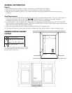
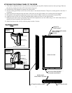
ATTACHING THE OVERLAY PANEL TO THE DOOR
1. If the door is attached to the unit, remove by unscrewing the top allen head set screw at the top hinge. Remove
the door by angling the door off of the bottom hinge pin.
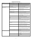
2. Peel back the door gasket to expose the screw holes.
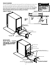
3. Set the overlay panel flush to the front of the door in the desired location. Clamp the overlay panel to the door if
necessary.
4. Insert the wood screws through the back of the door into the pilot holes in the overlay panel and tighten.
5. Reinstall the door gasket by pressing into the door channel. Make certain the corners are inserted fully.
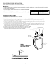
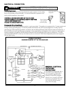
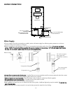
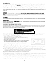
6. Install the door to the unit. Use the supplied plastic washer as shown in the figure below.
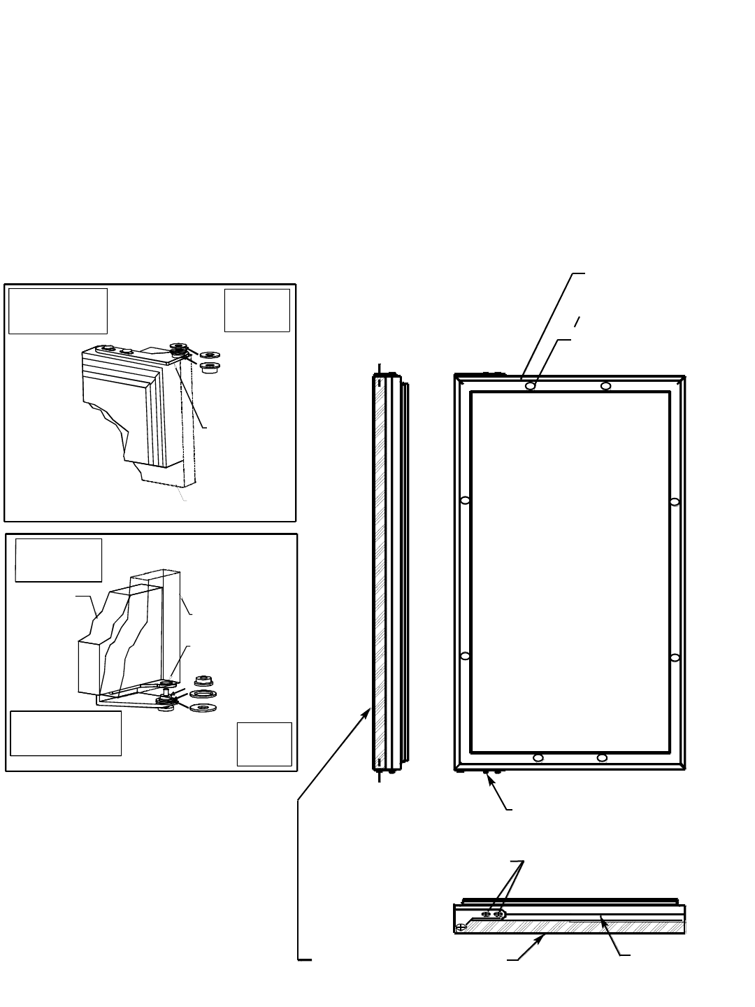
7. Realigning the door may be necessary. Any final door adjustments can be made using a 1/8” allen head driver to
adjust the door’s brackets. (See figure below)
8. Attach the door to the unit by reversing step number 1 above.
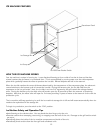
HHiinnggee HHaarrddwwaarree IInnssttaallllaattiioonn
DDeettaaiillss
MAGNETIC
DOOR GASKET
1/8 INCH ALLEN HEAD SCREWS
FOR HINGE ADJUSTMENT
ATTACHED OVERLAY PANEL
DOOR HINGE
ADJUSTMENT SCREWS
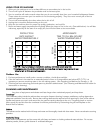
BOTTOM OF DOOR
REAR OF DOOR
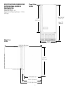
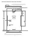
Ø0.38 CLEARANCE HOLES
FOR SCREWS
8 HOLES
DOOR HINGE
BUSHING BRACKET
TOP HINGE CORNER
SHOULDER BUSHING
WASHER
OVERLAY PANEL
.625 OD X .218 ID
HARDWARE
COMPONENTS
AT TOP HINGE
(2) NYLON
CAUTION
DOOR CAN BECOME
DISENGAGED IF
WASHERS ARE
NOT INSTALLED
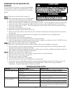
BOTTOM HINGE CORNER
DOOR HINGE
BUSHING BRACKET
SHOULDER BUSHING
.75 OD X .443 ID
.75 OD X .257 ID
OVERLAY PANEL
REFRIGERATOR
DOOR
WASHER
WASHER
CAUTION
DOOR MAY NOT SWING
PROPERLY IF ALL NYLON
COMPONENTS ARE NOT
INSTALLED AS SHOWN
(3) NYLON
HARDWARE
COMPONENTS
AT BOTTOM
HINGE
CAUTION
DOOR CAN BECOME
DISENGAGED IF
WASHERS ARE
NOT INSTALLED
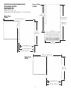
0 3/8” CLEARANCE HOLES
FOR SCREWS
8 HOLES
1/8” ALLEN HEAD SCREWS
FOR HINGE ADJUSTMENT