


98
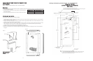
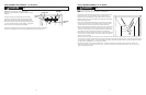
CCUUSSTTOOMM WWOOOODD FFRRAAMMEE IINNSSTTAALLLLAATTIIOONN IINNSSTTRRUUCCTTIIOONNSS
((DDFFUUWW MMooddeell))
Note: Weight of wood panel must not exceed 20 lbs.
W
W
o
o
o
o
d
d
S
S
c
c
r
r
e
e
w
w
s
s
1
. A #10 pan head wood screw should be used to properly secure the wood frame. A total of 10 screws will be needed.
2
. Only use pan head screws.
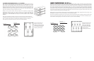
3. DO NOT select a screw that is longer than the wood thickness at
the screw locations.
4. Use recommended pilot holes for the frame material. (See chart)
WWoorrkkiinngg MMaatteerriiaall WWoooodd SSccrreeww SSiizzee ##1100
Hardwood 3/32 (0.24 cm)
Softwood 5/64 (0.20 cm)
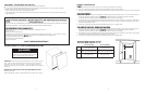
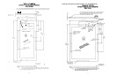
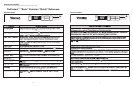
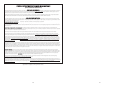
AAsssseemmbblliinngg DDoooorr HHiinnggee BBrraacckkeettss
(Disregard if hinge brackets are already attached)
1. Attach the top and bottom door hinge brackets to the door with the #10-32 machine screws and a 1/8” allen head
driver as shown in Figure 1 below.
2. Press in the shoulder bushings to the top and bottom door hinge brackets. Make certain that the shoulder is to the
outside of the door as shown in Figure 1 below.
3. Test fit the door to the unit to make certain door will hang correctly. The door is hung correctly when the top of the
door is parallel to the top of the unit. (See Figure 2) Adjustments can be made by loosening the door hinge
machine screws and moving the door hinge brackets on the door.
4. Tighten all four (4) machine screws after adjustments have been made.
5. Remove the door from the unit by removing the units top hinge set screw and angling the door off of the bottom
hinge pin.
Figure 1
Shoulder Bushing
Door Hinge Bracket
#10-32 Machine
Screw
Door Hinge
Screw Holes
Door Front
Surface
TTyyppiiccaall TToopp aanndd BBoottttoomm
DDoooorr HHiinnggee BBrraacckkeett
AAsssseemmbbllyy
Figure 2
This surface parallel to the unit.
(Right hinge door shown.)
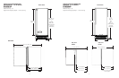
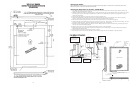
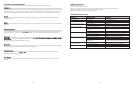
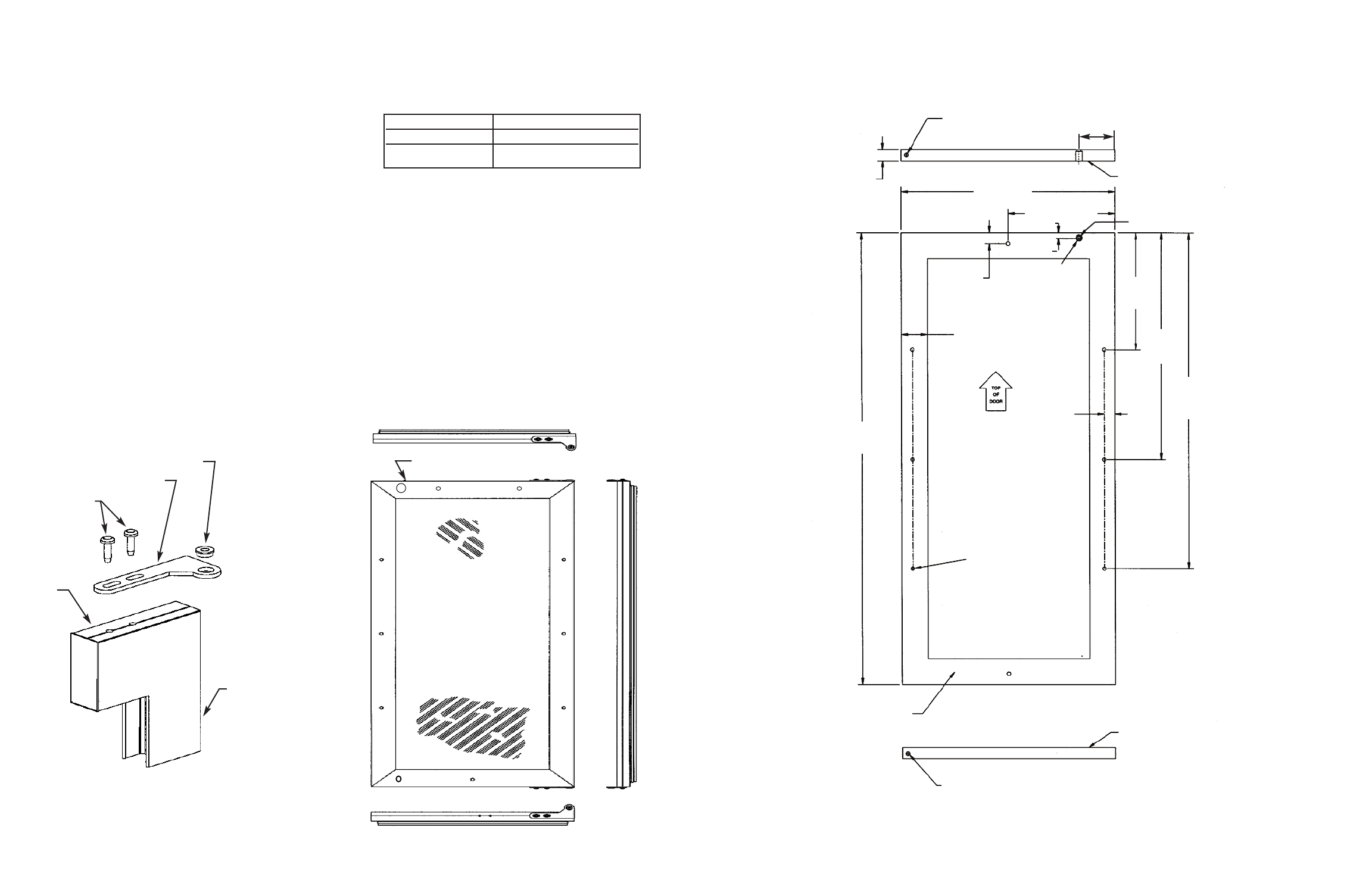
Selecting and Preparing the Wood Frame - 15” W. DFUW Model
FFOORR AA 33--11//22”” TTOOEE KKIICCKK
((CCOOVVEERRSS TTHHEE EENNTTIIRREE DDOOOORR EEXXTTRRUUSSIIOONN))
((LLEEFFTT HHIINNGGEE))
1/4” X 3/8” Deep hinge screw clearance hole
-Locate and drill using door hinge hole after the door has been aligned
to the unit and when the wood is positioned on door.
1/4” X 3/8” Deep hinge screw clearance hole. Locate and drill using
door hinge hole after the door has been aligned to the unit and
when the wood is positioned on door.
M
ounting surface
(
Non-face) side
Mounting surface
(non-face) side
Mounting surface
(non-face) side
M
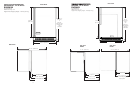
in. 5/8” (1.7 cm)
M
ax. 3/4” (1.9 cm)
1
4 5/16”
(
36.4 cm)
7 5/32” (18.2 cm)
23/32”
(1.8 cm) TYP
1
23/32” (4.4) cm min.
width to cover door
e
xtrusion
23/32”
(1.8 cm)
TYP
B
A
CK
V
IEW
O
F
O
V
ER
L
A
Y
PA
N
EL
30 5/16”
(77.0 cm)
Pre-drilled pilot holes -
8 places
7
13/16”
(
19.8 cm)
TYP
15 5/32”
(38.5 cm)
TYP
22 1.2”
(57.2 cm)
TYP
13/16” (2.1 cm)
counterbore 7/16”
(
1.1 cm) deep
1
5/32” (1.2 cm)
D
ia. hole
15./2” (1.2 cm)
3 7/32”
(
8.1 cm)