


13
Attaching the Wood Frame to the Door - DFUW Model
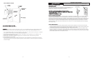
1. If the door is attached to the unit, remove by unscrewing the top allen head set screw at the top hinge. Remove the door by
angling the door off of the bottom hinge pin.
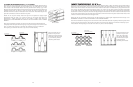
2. Install the supplied lock body into the wood panel. Secure the lock body by using the supplied 15mm lock retaining nut. Screw
the retaining nut onto the lock body’s threaded section. Make sure the lock’s key slot is vertical, then tighten the nut with a
15mm deep well socket.
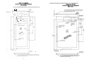
3. Peel back the door gasket to expose the screw holes and lock location hole.
4. Set the wood frame flush to the front of the door in the desired location. Clamp the wood frame to the door if necessary.
Check to make sure the back of the lock in the wood frame lines up with the hole in the door.
5. Insert the wood screws through the back of the door into the pilot holes in the wood frame and tighten.
6. Assemble the door lock’s phillips head screw, lock extension, and lock cam. Mount them to the back of the lock body. The cam
should be oriented vertically. Tighten the phillips head screw to secure the lock assembly.
7. Reinstall the door gasket by pressing into the door channel. Make certain the corners are inserted fully. Insert the key into the
lock and make sure lock operates properly.
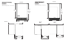
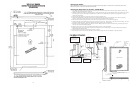
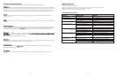
8. Install the door to the unit. Use the supplied plastic washer as shown in the figure below.
9. Realigning the door may be necessary. Any final door adjustments can be made using a 1/8” allen head driver to adjust the
door’s hinges. (See figure below)
10. Attach the door to the unit by reversing step number 1 above.
11. Insert the key into the lock and verify that the lock cam works properly with the catch bracket on the cabinet front.
C
AUTION
Door can become
disengaged if washers
are not installed.
CAUTION
Door can become
disengaged if
washers are not
installed.
Cabinet
Hinge
Wood
Frame
Door Hinge
Shoulder bushing
3/4” OD x 7/16”
ID Washer
3/4” OD x 1/4” ID
Washer
(3) Nylon hardware
components at
bottom hinge
CAUTION
Door may not swing properly
if all nylon components are
not installed as shown
Bottom Hinge Cover
Wood Frame
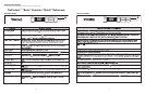
HHiinnggee HHaarrddwwaarree IInnssttaallllaattiioonn DDeettaaiillss
Magnetic door
gasket
Rear of Door
Bottom of door
Attached wood frame
5/8”x 7/32” ID washer
Shoulder
bushing
3/8” clearance
holes for
frame wood
screws -
10 holes
(
2) Nylon
hardware
components at
top hinge
Top Hinge Cover
1/8” allen head screws for hinge
adjustment
Door Hinge
Door hinge
adjustment screws
12
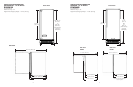
F
F
O
O
R
R
A
A
3
3
-
-
1
1
/
/
2
2
”
”
T
T
O
O
E
E
K
K
I
I
C
C
K
K
(
(
C
C
O
O
V
V
E
E
R
R
S
S
T
T
H
H
E
E
E
E
N
N
T
T
I
I
R
R
E
E
D
D
O
O
O
O
R
R
E
E
X
X
T
T
R
R
U
U
S
S
I
I
O
O
N
N
)
)
(
(
R
R
I
I
G
G
H
H
T
T
H
H
I
I
N
N
G
G
E
E
)
)
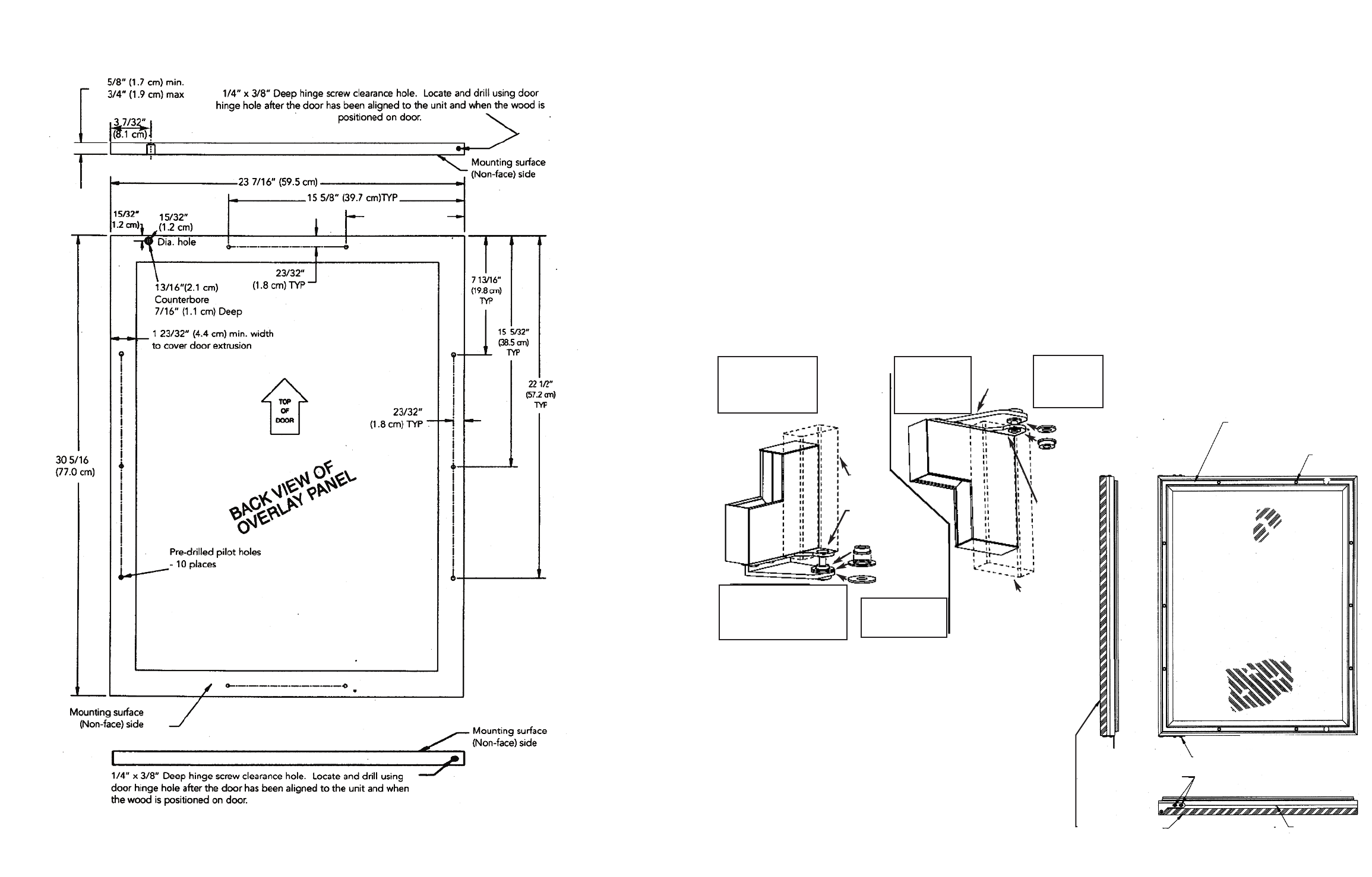
7 13/16” (19.8 cm)
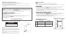
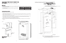
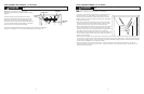
Attaching the Handle
Attach the handle of your choice by drilling mounting holes through panel. Countersink or counterbore holes from
backside of panel for handle screw heads to be flush.