


— 11 —
F35628 (10-04)
2. Units for operation of natural or propane
gas are also equipped with a factory preset
pressure regulator with an outlet pressure
of 5” W.C. (Water Column) for natural gas
supply and 10” W.C. for propane gas
supply, and should not require further
adjustment.
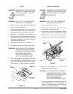
3. The burners and pilot flames may be
observed through round holes in the front
panel.
GAS PRESSURE MEASUREMENT
1. Set the power ON/OFF switch to the OFF
position.
2. Turn the gas supply off at manual shutoff
valve.
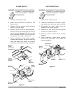
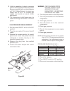
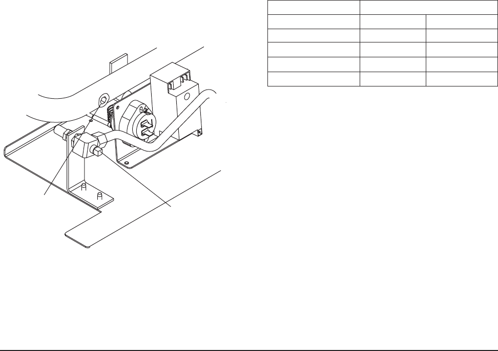
3. Remove the screws securing the control
panel and move the panel forward
sufficiently to access the plug on the
manifold pressure port.
4. Remove the plug from the manifold
pressure port.
5. Install hose barb adapter and attach
manometer tube.
Figure M
WARNING: THE FOLLOWING STEPS
REQUIRE POWER TO BE
APPLIED TO THE UNIT
DURING TEST. USE EXTREME
CAUTION AT ALL TIMES.
6. Turn the power switch to the ON position.
7. Turn only one burner on to the maximum
temperature.
8. Check gas pressure.
9. Turn all burners on to the maximum
temperature.
10.Check gas pressure.
11.Turn all other equipment on same supply
line on.
12.Check gas presssure.
NOTE: Pressure drop should not be greater
than ±½” W.C. If gas pressure requires
adjustment, the adjustment screw is
located under a cap on the regulator.
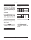
PRESSURE READINGS (IN W.C.)
Gas Type
Natural Propane
Manifold 5 10
Recommended 7-9 (Line) 11-12 (Line)
Minimum 6 (Line) 11 (Line)
Maximum 14 (Line) 14 (Line)
13.Turn off all burners.
14.Turn ON/OFF switch to OFF position.
15.Disconnect manometer and reinstall plug.
Manifold
Pressure
Port
Plug