


— 2 —
F35628 (10-04)
TABLE OF CONTENTS
GENERAL ........................................................................................................................................3
Introduction ................................................................................................................................3
Installation ..................................................................................................................................3
Operation....................................................................................................................................3
Cleaning .....................................................................................................................................3
Lubrication..................................................................................................................................3
Specifications.............................................................................................................................3
Tools ...........................................................................................................................................3
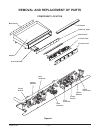
REMOVAL AND REPLACEMENT OF PARTS ..............................................................................4
Component Location .................................................................................................................4
Control Panel .............................................................................................................................5
Covers and Panels ....................................................................................................................5
Bullnose Weld Assembly ..........................................................................................................5
Heat Shield.................................................................................................................................5
Back Panel .................................................................................................................................5
Power On/Off Switch .................................................................................................................6
Indicator Light ............................................................................................................................6
Thermostat .................................................................................................................................6
Flame Switch..............................................................................................................................7
Ignitor Module ............................................................................................................................7
Gas Burner .................................................................................................................................8
Pilot Solenoid .............................................................................................................................8
Pilot .............................................................................................................................................9
Dual Solenoid.............................................................................................................................9
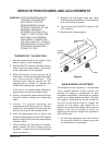
SERVICE PROCEDURES AND ADJUSTMENTS...................................................................... 10
Thermostat Calibration........................................................................................................... 10
Main Burner Adjustment ........................................................................................................ 10
Gas Pressure Measurement .................................................................................................. 11
Extended Shutdown ............................................................................................................... 11
ELECTRICAL OPERATION ......................................................................................................... 12
Component Description.......................................................................................................... 12
Sequence of Operation .......................................................................................................... 12
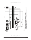
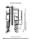
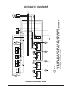
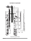
SCHEMATIC DIAGRAMS ............................................................................................................ 13
TROUBLESHOOTING GUIDE..................................................................................................... 18
© VULCAN-HART, 2004