


F35425 (February 2006)Page 23 of 40
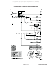
C24GA SERIES CONVECTION STEAMERS - ELECTRICAL OPERATION
1. Turn power switch on.
A. Timer de-energized.
1) Operating voltage applied to control
compartment after cavity relay is
latched on.
B. Water level control (WLC) energized.
1) Low level (LL) relay N.C. contacts
provide operating voltage to fast-fill
solenoid.
a. Fast-fill solenoid energized, water
begins filling the generator.
2) Water reaches low level probe.
a. LL relay N.C. contacts open and
N.O. contacts close.
b. Voltage applied to normally closed
pressure switch (opens at 4.0 psi).
c. Voltage applied through HL
contacts to hold thermostat
(closes at 190°F).
d. Voltage through pressure switch
applied to blower and to normally
open air switch (closes at
0.4" W.C.).
e. Fast-fill solenoid de-energized.
C. Air switch closes at 0.4" W.C.
1) Voltage applied to step-down
transformer primary (120 VAC).
Transformer steps voltage down to 24
VAC to operate ignition module.
2) Voltage applied to PV terminal of gas
valve and applying voltage to pilot valve
and high voltage spark lead to ignite
pilot.
3) Flame sensor sends signal to MV
relay. 1 micro-amp or higher is required
to maintain pilot.
4) MV relay contacts close and
energizes main valve.
5) Main burner ignites.
D. When temperature reaches 190°F, hold
thermostat closes energizing the slow-fill
solenoid to keep generator full.
E. When generator pressure reaches 4 psi, the
pressure switch N.C. contacts open, the
N.O. contacts close.
1) Voltage is removed from:
a. Air pressure switch.
b. Blower motor.
c. Step-down transformer which
removesvoltage from ignition
module.
F. Voltage through the N.O. contacts of the
pressure switch is applied to the cavity
relay in the compartments.
1) Voltage applied to compartment
controls after cavity relay is energized.
Relay remains energized until main
power is removed.
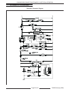
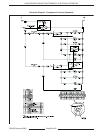
Compartment control (Units before Dec. 1, 2005)
Refer to schematic diagrams 00855693 & 00855424.
1. Compartment door closed causing door switch
to close and READY light to illuminate.
A. 120 VAC applied through door switch to
timer contact 1.
B. Timer manually set to desired time period.
C. Voltage applied through contacts 1 and 3.
1) Timer begins countdown.
2) Steam solenoid energized allowing
steam into compartment.
3) Cavity relay 1 energized, energizing
the CWC solenoid.
4) Cook Light illuminated.
D. Timer times out.
1) Timer contacts 1 – 3 open turning off
steam solenoid and cook light.
2) Timer contacts 1 – 4 close, turning on
buzzer.
E. Buzzer manually shut off by rotating timer
to off position.
2. Power switch set to off position.
A. Power removed from compartment controls
and generator control circuit.
B. Time delay relay energized.
1) Delay relay starts 1000-second
countdown.
2) Drain solenoid energized for 1000
seconds.
3) Water drained from generator.