F35425 (February 2006)Page 9 of 40
MAIN BURNER
WARNING: DISCONNECT THE
ELECTRICAL POWER TO THE
MACHINE AND FOLLOW LOCKOUT /
TAGOUT PROCEDURES.
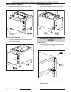
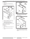
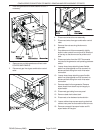
1. Remove front and side covers as outlined under
COVERS AND PANELS.
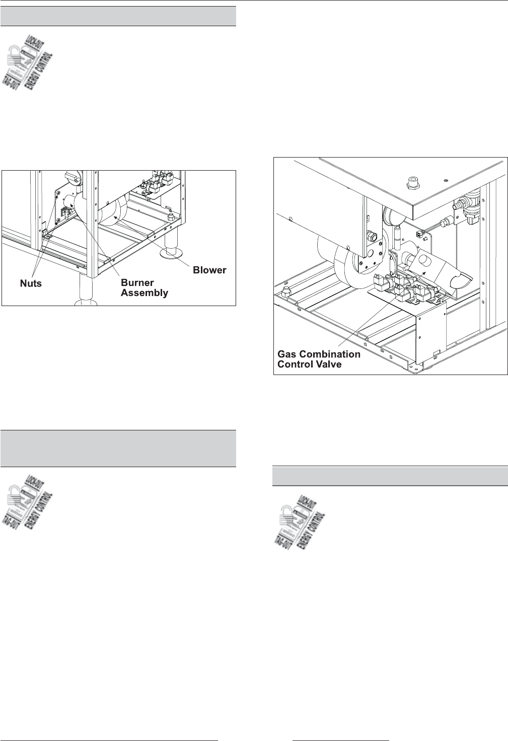
2. Disconnect the gas line at gas combination
control valve.
3. Disconnect wires to burner assembly.
4. Remove the nuts securing burner to tank.
5. Drop blower end of burner assembly slightly
down to clear control box and push all interfering
wires out of the way so that burner can be pulled
out of tank.
6. Reverse procedure to install burner assembly.
GAS COMBINATION
CONTROL VALVE
WARNING: DISCONNECT THE
ELECTRICAL POWER TO THE
MACHINE AND FOLLOW LOCKOUT /
TAGOUT PROCEDURES.
WARNING: SHUT OFF THE GAS SUPPLY BEFORE
SERVICING THE UNIT.
WARNING: ALL GAS JOINTS DISTURBED DURING
SERVICING MUST BE CHECKED FOR LEAKS.
CHECK WITH A SOAP AND WATER SOLUTION
(BUBBLES). DO NOT USE AN OPEN FLAME.
A. CHECK ALL JOINTS PRIOR TO THE GAS
VALVE (SOLENOID) BEFORE LIGHTING
THE UNIT.
B. CHECK ALL JOINTS BEYOND GAS VALVE
(SOLENOID) AFTER UNIT IS LIT.
Gas combination control valves are not serviceable
and should not be disassembled. Once the problem
has been isolated to this control, replace it. Do not
attempt to repair the assembly.
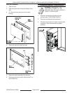
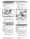
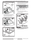
1. Remove the front and right side panels as
outlined under COVERS AND PANELS.
2. Remove main burner as outlined in MAIN
BURNER.
3. Disconnect electrical supply wires running to the
gas combination control valve.
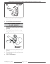
4. Disconnect the pilot gas supply tube from the
control and pipe connections on each side of the
gas combination control valve.
5. Reverse procedure to install and check unit for
proper operation.
GENERATOR ASSEMBLY
WARNING: DISCONNECT THE
ELECTRICAL POWER TO THE
MACHINE AND FOLLOW LOCKOUT /
TAGOUT PROCEDURES.
WARNING: SHUT OFF THE GAS SUPPLY BEFORE
SERVICING THE UNIT.
WARNING: ALL GAS JOINTS DISTURBED DURING
SERVICING MUST BE CHECKED FOR LEAKS.
CHECK WITH A SOAP AND WATER SOLUTION
(BUBBLES). DO NOT USE AN OPEN FLAME.
A. CHECK ALL JOINTS PRIOR TO THE GAS
VALVE (SOLENOID) BEFORE LIGHTING
THE UNIT.
B. CHECK ALL JOINTS BEYOND GAS VALVE
(SOLENOID) AFTER UNIT IS LIT.
C24GA SERIES CONVECTION STEAMERS - REMOVAL AND REPLACEMENT OF PARTS


