F35425 (February 2006)Page 29 of 40
C24GA SERIES CONVECTION STEAMERS - ELECTRICAL OPERATION
COMPONENT FUNCTION
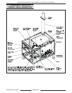
CABINET BASE GENERATOR
Water Level Control and
Level Sensing Probes...................The Water Level Control circuit board and Level Sensing Probe Assembly
allow water to enter the generator to fill and maintain the proper water level.
These probes will also shut off the heat source to the generator if the water
level drops too low.
The water level control works by using three different probe lengths to monitor
the water level. The probes consist of a high level (HL), low level (LL), and low
water cut-off (LLCO) probe. The level sensing probes may easily be removed to
inspect for lime build up. As a rule, the condition of these devices will indicate
the overall water condition of the generator. Clean the probes, if necessary.
Generator Fast Fill
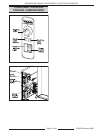
Solenoid Valve............................. The Generator Fast Fill Solenoid Valve is located on the right side of the
base and admits water at rate of 3.7 GPM to the generator when demanded by
the water level control to maintain the correct water level in the generator.
Generator Slow Fill
Solenoid Valve............................. The Generator Slow (Trickle) Fill Solenoid Valve is located on the right side of
the base and admits water to the generator at a rate of 0.25 GPM when
demanded by the water level control to maintain the correct water level in the
generator.
The output of the Fast Fill and Slow Fill valves are connected in a “Y” to provide
a single feed to the generator.
Cold Water Condenser (CWC)
Solenoid Valve............................. The Cold Water Condenser (CWC) Solenoid Valve allows cold water to flow
into the generator drain to condense steam and cool the hot water before it is
discharged into the drain.
Cavity Cold Water
Solenoid Valve............................. The Cavity Cold Water Solenoid Valve allows cold water to flow into the
cavity drain and cool the hot water before it is discharged into the drain.
Operating Pressure Switch........... The Pressure Switch is located on the front upper right corner of the
generator and is accessible through the left side panel. This switch controls
generator pressure between prescribed limits by turning the heat source on
and off.
Drain Solenoid Valve.................... The Drain Solenoid Valve (Drain Valve) is located on the right side of the base
and is plumbed into the drain pipe of the generator. The generator will
automatically drain for 1000 seconds when power is turned off by using a
normally closed solenoid valve. Daily generator draining is essential to proper
operation and component life by removing sediment and scalants that may be
lodged in the chamber of the generator.
Strainers....................................... Strainers are used in the water inlet line to prevent foreign matter from
becoming lodged in the fill or cold water condenser solenoid valves and to keep
unwanted particles out of the system. Strainers are also located in the steam
line and drain line.
Pressure Gauge
(If applicable)................................The Pressure Gauge is located on the upper right front of the base and indi-
cates generator steam pressure.
Cold Water Thermostat.................The Cold Water Thermostat is located on the lower right side of the base and
maintains drain temperature below 140°F by controlling the drain CWC
solenoid.


