


SERVICE PROCEDURES AND ADJUSTMENTS
Certain procedures in this section require electrical test or measurements while power is applied
to the machine. Exercise extreme caution at all times. If test points are not easily accessible, disconnect power and
follow lockout / tagout procedures, attach test equipment and reapply power to the test.
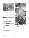
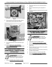
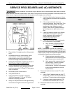
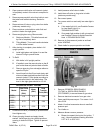
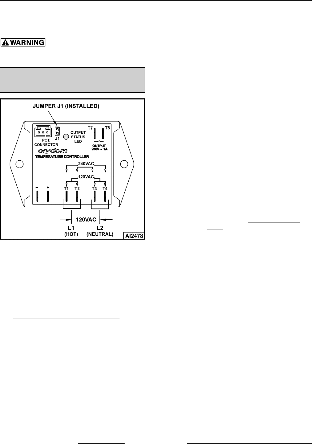
TEMPERATURE CONTROLLER
TEST
Fig. 33
1. Place kettle in full upright position (tilting models
only).
2. Set temperature dial to lowest setting. Kettle
must be below 110°F before verifying the
potentiometer output to the controller is good
over the full range of temperature dial travel.
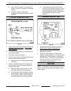
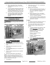
3. Access the temperature controller as outlined in
ELECTRICAL PANEL COMPONENTS.
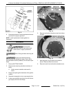
4. Check all lead wires for secure connections to the
controller terminals. Wiring harness lead wires
must be connected to T1-T2 and T3-T4 for proper
input to controller.
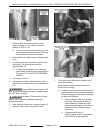
5. Re-connect power to the machine.
6. Turn power switch on.
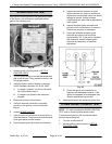
7. Verify temperature controller is receiving
120VAC at terminals T1-T3 and T2-T4 and
machine is properly grounded.
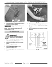
8. Slowly turn temperature dial to the highest setting
and monitor heat light over the full range of travel.
A. Verify heat light (amber) comes on, blower
motor comes on and transformer is powered
(120VAC).
B. If the components listed above are
functioning properly, then output from T8 on
controller should be present. As long as
transformer output voltage is correct
(24VAC), heat circuit is powered and the
ignition sequence to light the burner will
start.
C. If heat light does not remain on or flashes
momentarily as temperature setting is
slowly increased, verify condition of
potentiometer as outlined under
POTENTIOMETER TEST.
D. If heat light or blower motor is not coming
on; or transformer is not powered.
1) Verify condition of thermocouple as
outlined under THERMOCOUPLE
TEST.
NOTE: Temperature controller will de-energize
internal relay and turn off the output status LED if the
circuitry detects an open thermocouple. LED will begin
to flash 3 times, pause, then repeat the flash sequence
to indicate the open thermocouple condition.
2) Check lead wire connections at the
component that is not functioning (heat
light, blower motor or transformer).
3) Verify power at the component that is
not functioning. If power is present,
determine if the component is
malfunctioning. If power is not present
at any of the components, continue
with procedure.
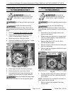
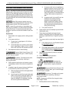
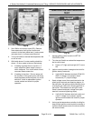
9. Disconnect lead wire from terminal T7 on the
controller.
A. Verify 120VAC between lead wire from T7
and ground. If correct, re-connect lead wire
to terminal T7 and continue with procedure.
B. If incorrect, check pressure switch (1PS)
and water level controller (WLC LLCO).
10. Disconnect lead wire from terminal T8 on the
controller.
K Series Gas Kettles 2/3 Jacketed Stationary and Tilting - SERVICE PROCEDURES AND ADJUSTMENTS
F45461 Rev. A (0713) Page 18 of 44