ELECTRIC BRAISING PANS - SERVICE PROCEDURES AND ADJUSTMENTS
F35410 (May 2003) Page 18 of 32
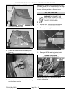
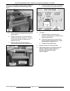
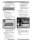
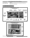
SIDE VIEW SHOWN
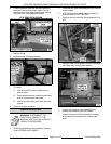
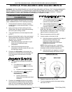
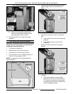
LEFT SIDE VIEW SHOWN
A. If voltage is present but pan does not
raise, refer to MOTORIZED LIFT OPTION
ONLY under TROUBLESHOOTING.
B. If voltage is not present and the fuse is ok,
turn the on/off switch off and disconnect
power to the machine.
11. Install a replacement DC motor controller and
check for proper operation.
PAN POSITION/DOWN LIMIT
SWITCH ADJUSTMENT
NOTE: Do not use the motorized lift (if installed) for
this procedure.
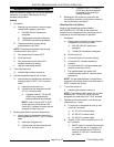
1. Turn the on/off switch off.
2. Remove front and left side panels as outlined
under COVERS AND PANELS.
3. Insert the manual crank handle.
4. Raise the pan to the full tilt position.
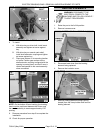
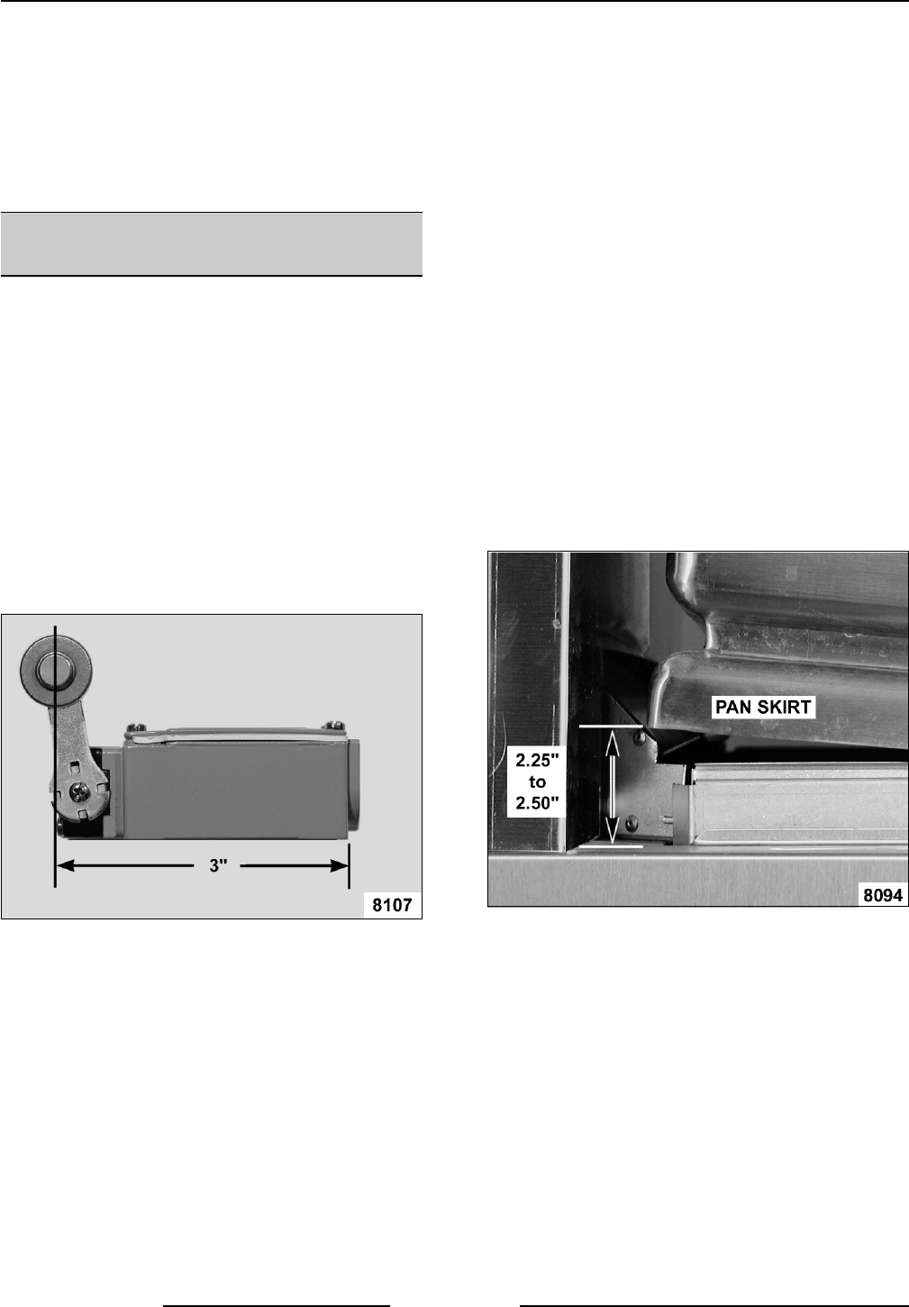
5. Verify roller arm position on switch.
A. Measure the distance from the rear of the
switch body to the center of the roller. The
distance should be 3".
B. If distance is ok, proceed to step 6.
C. If distance is not ok, position the roller arm
as outlined under PAN POSITION/DOWN
LIMIT SWITCH in REMOVAL AND
REPLACEMENT OF PARTS.
6. Lower the pan to the full down position. The
roller should make contact with the hinge and
operate the switch.
7. Verify pan position/down limit switch N.O.
contacts are closing.
A. Turn the on/off switch on and set the
temperature dial to call for heat.
B. Heat light (red) comes on and all heating
elements are energized.
1) If heating elements do not energize:
Verify 24VAC input to the switch and
24VAC is output from the switch.
2) If voltage is present on the output
side of the switch, the switch is
functioning properly. See
TROUBLESHOOTING.
3) If voltage is not present on the output
side of the switch, install a
replacement pan position/down limit
switch and repeat this procedure to
adjust.
8. Verify pan position/down limit switch N.O.
contacts are opening.
A. Slowly raise the pan until the heat light
and heating elements de-energize then
stop.
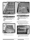
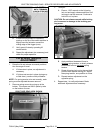
B. At the rear of the pan, measure the
distance from the bottom of the pan skirt
to the flat surface covering the frame.
1) Distance should be 2.25" to 2.50".
NOTE: For reference, this is approximately 5
angular degrees.
9. If heat light and heating elements de-energize;
and the measured distance is within the
acceptable range, switch is adjusted properly.
If both conditions are not satisfied, adjustment
is necessary.
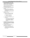
10. To Adjust:
A. Loosen screws on the mounting switch
bracket.


