ELECTRIC BRAISING PANS - REMOVAL AND REPLACEMENT OF PARTS
F35410 (May 2003) Page 8 of 32
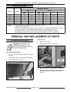
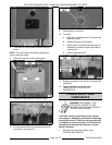
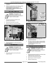
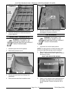
SIDE VIEW SHOWN
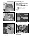
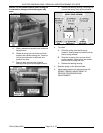
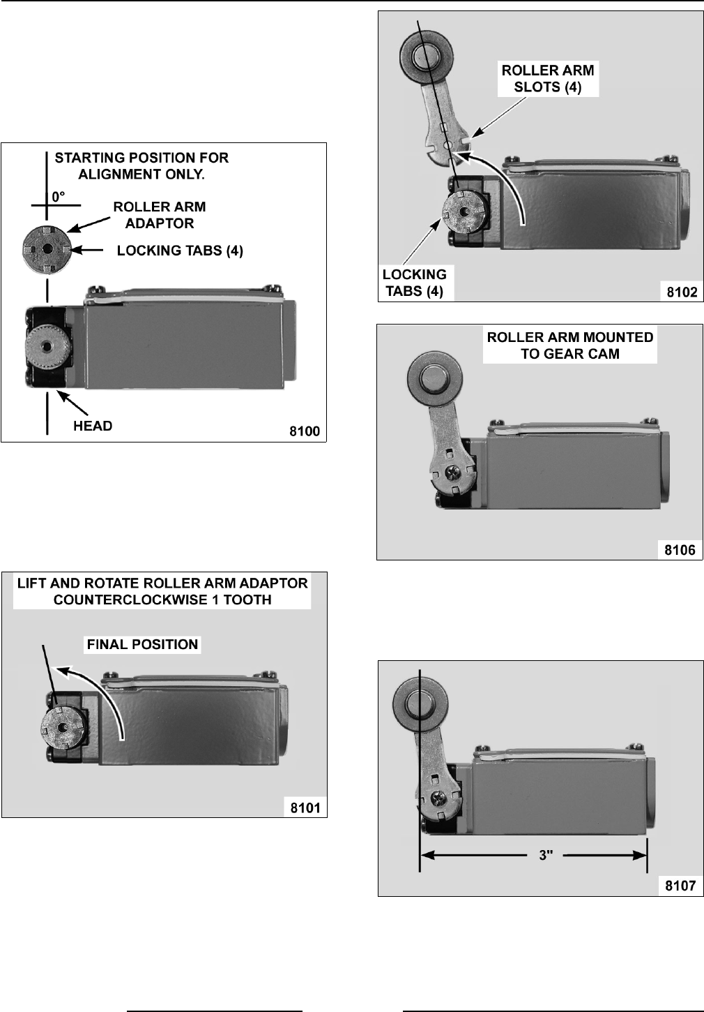
D. Align roller arm adaptor with the four
locking tabs pointing up and position one
of the tabs at 0°.
NOTE: The 0° position of the roller arm locking tab
is the starting point for alignment only. The locking
tab cannot remain at the 0° position.
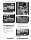
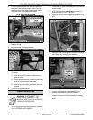
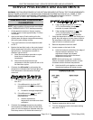
E. Place roller arm adaptor on the gear cam
to engage the teeth. Lift the adaptor until
the teeth just slightly disengage from the
gear cam. Rotate the roller arm adaptor
counterclockwise 1 tooth, re-engage teeth
and release the adaptor.
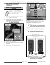
F. Align the roller arm slots with the four
locking tabs on the roller arm adaptor and
tighten mounting screw to secure.
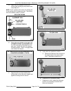
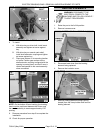
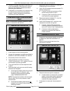
G. Verify roller arm position on switch.
1) Measure the distance from the rear of
the switch body to the center of the
roller. The distance should be 3".
H. If distance is ok, proceed to step 7.
I. If distance is not ok, adjust the roller arm
position (as necessary) to obtain the 3"
roller arm dimension.


