


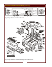
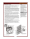

ITEM
1.
a6.
8.
9.
a10.
a11.
12.
a15.
16.
18.
19.
22.
23.
28.
a31.
38.
40.
41.
42.
43.
44.
53.
56.
V1
V2
V3
V4*
V5*
V6*
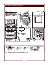
DESCRIPTION
NAMEPLATE
FIRE SUPPRESSION AGENT
TANK (1.5 gal.)
ADJUSTABLE (FRONT) LEG
RIGID (REAR) CASTER
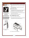
MANUAL PULL STATION
FUSIBLE LINKS
LOWER REAR ACCESS PANEL
DISCHARGE NOZZLE
GREASE BAFFLE
PRE-FILTER ASSEMBLY
HEPA/CHARCOAL FILTER PACK
GREASE CUP
GREASE TROUGH
VENTILATOR EXHAUST DUCT
STATUS INDICATOR
POWER CORD (
WHEN PROVIDED
)
WARMER RELAY
POWER CONTACTOR
BUILDING FIRE ALARM RELAY
GROUND LUG
INTERLOCK TERMINAL
FILTER INTERLOCK SWITCHES
VENTILATOR FAN
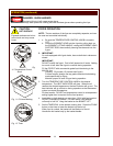
POWER SWITCH
POWER ON INDICATOR
CHECK FILTERS ALARM
INDICATOR
REPLACE PREFILTER ALARM
INDICATOR
REPLACE FILTER PACK ALARM
INDICATOR
SERVICE REQUIRED ALARM
INDICATOR
COMMENT
Lists Manufacturer, Model and Serial Number information.
Also lists electrical specifications.
Container for Ansulex™ Low-pH liquid fire suppression liquid.
Allows the unit to be leveled.
Allows the unit to be easily positioned by lifting the front of the unit slightly.
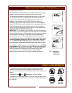
Provides a means of manual activation of the fire suppression system.
PULL ONLY IN CASE OF FIRE!
Automatically activates fire suppression system in the event of fire in the fryer.
Allows access to Ansul® fire suppression agent tank (a6) and controls also
access to main power contactor (41).
Fire suppression media discharges here (2 places).
Extracts and drains most grease and moisture from the air flow.
Comprises the PRE-FILTER FRAME and a replaceable
PRE-FILTER. Stops larger particles of grease from reaching the FILTER
PACK for reduced maintenance costs.
Stops most grease and smoke particles. Also assists in some cooking odor
removal.
Collects grease/moisture drained from grease trough (23).
Directs grease/moisture removed by grease baffle to grease cup.
Exit point for ventilator airflow - on top left rear of unit.
DO NOT BLOCK
Displays status of fire suppression system (COCKED - FIRED). If FIRED, a
buzzer will sound continuously.
6’ cord and cap. Plug for NEMA 15-60R (receptacle by user).
Provides power to roll warmer section. Energized at all times except during fire
safety shut-down.
Energizes fryer only while ventilator section is sensed as operational.
Reports fire alarm condition to building fire management system.
Ground wire of power cord connects here.
Provides connection for shut-down control by building fire management system.
Proper installation of grease baffle and filter pack close these switches in
ventilator sensor circuit.
Provides air movement for ventilation.
Energizes blower motor. If, after 10 seconds, proper conditions are met,
appliance is energized.
GREEN. Glows when POWER switch is ON.
AMBER. Glows if one or more filters are out of position. Check all filters and
baffles for proper installation.
AMBER. Glows when PREFILTER is approaching the end of its service life and
must soon be replaced.
AMBER. Glows when FILTER PACK is approaching the end of its service life
and must soon be replaced.
RED. Glows when PREFILTER and/or FILTER PACK has reached the end of
its service life and is too loaded to allow sufficient air flow. Filter MUST be
replaced. Appliance is SHUT DOWN until expended filters are replaced.
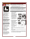
FEATURES & OPERATING CONTROLS (continued)
VENTILATOR SECTION
3
VENTILATOR CONTROL AND INDICATOR PANEL
* See PRECAUTIONS & GENERAL INFORMATION, pages 6 & 7 for special procedures regarding prefilters and filter packs.