


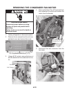
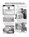
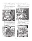
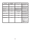

5-2
N/A
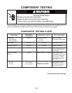
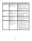
Will have 115 VDC at
Dispenser Motor termi-
nals 1 & 5. DC polarity
determines the rotation
of the motor:
Terminal 1 5
Crushed: – +
Cube: + –
Ice Dispenser Motor
COMPONENT TEST LOCATIONS
Electronic Control Board Will have 120V at
Control Board terminals
3 & 2.
User Interface Board
Will have 120V at User
Interface pins 5/3 & 5/1.
Defrost Heater
550 to 650 Watts
27 to 21 Ω
Check resistance at
Control Board terminals
16/1 & 12/1 or at heater.
Evaporator Fan Motor
3 Watts
Cannot read resistance/
120 VAC converted to
DC voltage in the motor.
Condenser Fan Motor
5 Watts
Defrost Bimetal
Check for continuity.
VOLTAGE AT
COMPONENT
RESISTANCE / WATTS
N/A120 VAC
120 VAC
N/A
120 VAC
Opens @ 45ºF±5º (7ºC±3º)
Closes @ 19ºF±5º (–7ºC±3º)
Opens @ 162ºF (72ºC)Thermofuse
120 VAC
120 VAC
120 VAC
120 VAC
120 VAC
Cannot read resistance/
120 VAC converted to
DC voltage in the motor.