


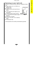
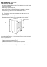

Install the gas supply pipe on site complete with the union elbow (See Fig.6). Note the orientation of the
elbow.
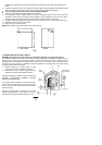
8 Position the appliance in front of the cabinet and run the supply cable (See Section 2) through the cabinet
and connect to the junction box or socket. Ensure that the supply is isolated at this stage.
N.B. Two people will be required to carry out the lifting procedure.
Warning: Do not attempt to lift this appliance by the handle.
9 Lift the appliance into the cabinet making sure the gas supply pipe enters the duct in the rear of the
appliance and the cable is not trapped by the appliance. Push the appliance as far back as it will go.
Ensure the supply pipe comes through the control panel and pull through any slack cable.
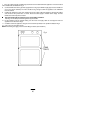
10 Centralise and fix the appliance to the cabinet using six wood screws in the position indicated in Fig.4
11 Tighten the union nut into the supply elbow.
12 Carry out a gas soundness check.
NOTE:Check supply pressure before fitting fascia (See Section 3).
2. CONNECTION TO ELECTRICITY SUPPLY
WARNING:This appliance must be earthed, do not earth this appliance to the gas supply piping.
This appliance must be connected to a 220V-240V AC. 50Hz supply which incorporates a 3 ampere fuse. If
any other type of plug is used it should incorporate a 5 ampere fuse either in the plug or adapter or at the
distribution board. The appliance is supplied with 2 meters (6.5 ft) of 5 ampere 3 core cable fittted with a
moulded plug. If this proves to be insufficient to allow the appliance to be plugged into the nearest supply
socket, the supply cable can be either:
i) Replaced totally by a longer cable at least
0.75mm² nominal cross sectional area (24/0.2).
ii) Extended by using a B.E.A.B. approved 3-way
sealed flex connector with integral flex clamps.
DO NOT EXTEND THE CABLE USING PLASTIC OR
CERAMIC CONNECTION TERMINAL BLOCKS
AND/OR INSULATION TAPE.
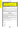
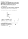
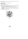
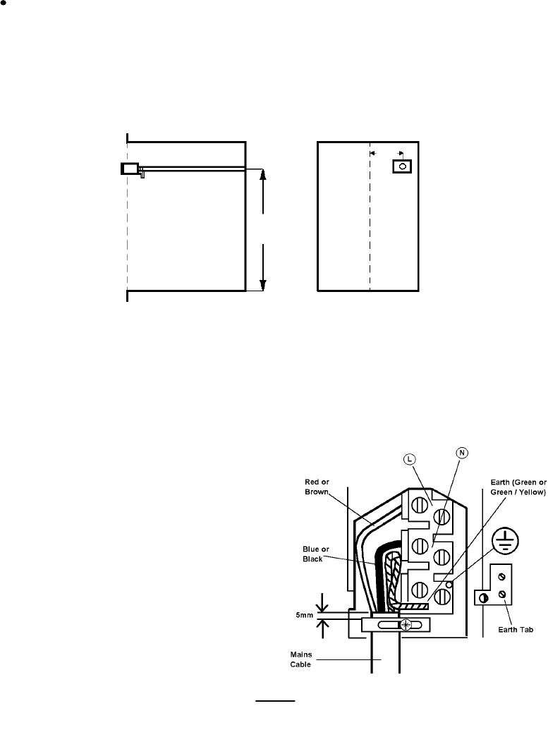
If the supply cable is replaced it is recommended that
the ends of the new cable all be cut to the same length
60mm, any excess wire being stored inside the mains
terminal see Fig.7.
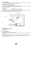
Should the supplied cable be required to be threaded
through small apertures in the cabinets it can be
removed from the mains inlet terminal block see Fig.7.
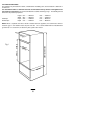
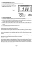
42
795
FRONT
225
mm
SIDE VIEW
Fig.6
Fig.7