


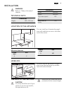


B
60 mm
50 mm
A
60 mm
A
50 mm
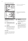
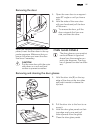
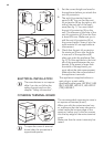
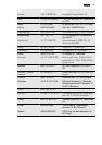
1.
Set the correct height and area for
the appliance before you attach the
anti-tilt protection.
2.
The anti-tilt protection has two
parts (A+B). You can find the anti-
tilt protection (B) on the right or left
side of the rear wall of the appli-
ance (See fig. 1). You must install
the anti-tilt protection (A) on the
wall. The distance of the hole of the
anti-tilt protection (A) from the floor
is about 816 mm. Make sure you in-
stall the anti-tilt protection (A) at
the correct height. Screw it into the
solid material or use applicable re-
inforcement.
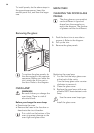
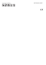
3.
Check that the anti-tilt protection
fits minimum 20 mm into the hole
in rear wall of the appliance (B)
when you push the appliance (See
fig. 2). Put the appliance in the mid-
dle of the space between the cup-
boards. If the space is larger than
the width of the appliance, you
must adjust the side measurement.
Make sure that the surface behind
the appliance is smooth.
ELECTRICAL INSTALLATION
The manufacturer is not respon-
sible if you do not follow the
safety precautions from the
chapter "Safety information".
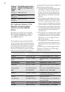
This appliance is supplied without a
main plug or a main cable.
Applicable cable types: H07 RN-F, H05
RN-F, H05 RRF, H05 VV-F, H05 V2V2-F
(T90), H05 BB-F.
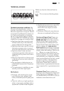
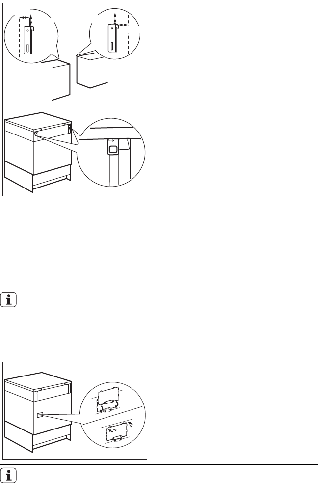
COVERING TERMINAL BOARD
The recommended cross-section area is
six square millimetres (6 mm²).
When you refit the mains terminal cov-
er, make sure that the lower tabs are lo-
cated inside the bottom edge of the
aperture, before you fix the two screws
into the top edge of the mains terminal
cover.
Make sure that the cover is securely fas-
tened.
To open the cover of terminal
board obey the procedure in
opposite sequence.
42