


6
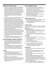
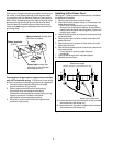
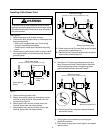
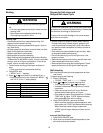
Anti-tip Bracket Installation
To reduce risk of range tipping, secure range with a
properly installed anti-tip bracket. (Figure 3)
1. Measure 3
1
/2 inches from back wall on right and left
side of cabinet cutout. Mark measurements on floor
and draw a straight line connecting marks.
2. Position anti-tip bracket.
• If range is installed beside cabinet(s), place anti-tip
bracket with back edge on line drawn on floor and
side of bracket against cabinet.
• If range is not installed beside cabinet(s), position
range where it will be installed. Draw a line along
side of range on floor from front to back. Remove
range. Place anti-tip bracket with back edge over
line drawn 3
1
/2 inches from back wall and side of
bracket over line drawn along side of range on floor.
• Anti-tip bracket can be installed on either right or
left side.
or
3 1/2"
Figure 3
3. Mark 2 hole locations in anti-tip bracket.
4. Drill 2 holes.
• If drilling into wood, use a
3
/32-inch drill bit.
• If drilling into concrete, use a
3
/16-inch masonry drill
bit and insert plastic anchors.
5. Secure bracket to floor using screws supplied. Slide
range into position.
6. Remove range storage drawer or lower panel and
confirm anti-tip bracket is engaged with range
leveling leg.
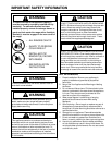
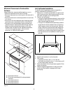
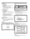
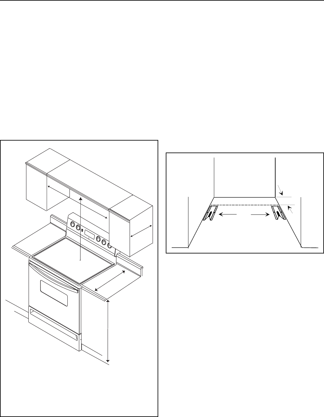
Minimum Clearances to Combustible
Surfaces
Using dimensions, prepare cabinet opening. (Figure 2)
• Minimum clearance to rear wall is 0 inches.
• Minimum clearance to a vertical right or left side wall is
0 inches.
• Minimum clearance to countertop/cabinet on each side
is 0 inches.
• Minimum of 30 inches between top of cooking surface
and bottom of an unprotected wood or metal cabinet.
• Minimum of 24 inches between cooking surface and
protected wood or metal cabinet above range. Cabinet
bottom must be protected by at least ¼ inch thick
millboard with not less than No. 28 MSG sheet steel,
.015 inch thick stainless steel, .024 inch thick
aluminum, or .020 inch thick copper.
A
B
C
D
E
A—30 inches minimum
B—30 inches unprotected/24 inches protected
minimum
C—13 inches maximum
D—25 inches maximum
E—36 inches maximum
Figure 2