


AD8342
Rev. 0 | Page 3 of 20
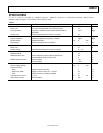
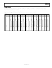
SPECIFICATIONS
V
S
= 5 V, T
A
= 25°C, f
RF
= 238 MHz, f
LO
= 286 MHz, LO power = 0 dBm, Z
O
= 50 Ω, R
BIAS
= 1.82 kΩ, RF termination = 100 Ω, IF termi-
nated into 100 Ω through a 2:1 ratio balun, unless otherwise noted.
Table 1.
Parameter Conditions Min Typ Max Unit
RF INPUT INTERFACE
Return Loss Hi-Z input terminated with 100 Ω off-chip resistor 10 dB
Input Impedance
Frequency = 238 MHz (measured at RFIN with RFCM ac-
grounded)
1||0.4 kΩ||pF
DC Bias Level Internally generated; port must be ac-coupled 2.4 V
OUTPUT INTERFACE
Output Impedance Differential impedance, frequency = 48 MHz 10||0.5 kΩ||pF
DC Bias Voltage Supplied externally 4.75 V
S
5.25 V
Power Range Via a 2:1 impedance ratio transformer 13 dBm
LO INTERFACE
Return Loss 10 dB
DC Bias Voltage Internally generated; port must be ac-coupled V
S
− 1.6 V
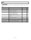
POWER-DOWN INTERFACE
PWDN Threshold 3.5 V
PWDN Response Time Device enabled, IF output to 90% of its final level 0.4 µs
Device disabled, supply current <5 mA 4 µs
PWDN Input Bias Current Device enabled −80 µA
Device disabled +100 µA
POWER SUPPLY
Positive Supply Voltage 4.75 5 5.25 V
Quiescent Current
VPDC Supply current for bias cells 5 mA
VPMX, IFOP, IFOM Supply current for mixer, R
BIAS
= 1.82 kΩ 58 mA
VPLO Supply current for LO limiting amplifier 35 mA
Total Quiescent Current V
S
= 5 V 85 98 113 mA
Power-Down Current Device disabled 500 µA