


OPERATION INFRARED CHEESE MELTER
PAGE 8 OF 28 INSTALLATION AND OPERATION MANUAL 1186533 REV 1 (02/06)
OPERATION
DANGER
EXPLOSION HAZARD
In the event a gas odor is detected, shut down equipment at the main shutoff valve. Immediately call the
emergency phone number of your gas supplier.
CAUTION
If the Cheese Melter pilots should go out the flow of gas to the Cheese Melter burners is NOT interrupted.
Consequently, it is the responsibility of the operator to check the ignition of the burners immediately EVERY TIME
the Cheese Melter is turned on. Should ignition fail after 10 seconds, turn off burners, wait 5 minutes, and then try
again.
NOTICE
Blodgett Range infrared Cheese Melters cook food in about half the time of conventional Cheese Melters, so
adjust cooking times.
Blodgett Range infrared Cheese Melters are unique in design. They incorporate our exclusive ceramic tile burners,
which generate infrared rays that provide better quality products in about one-half the usual broiling time, and with
less gas input than ordinary Cheese Melters. Very little energy is wasted in heating secondary surfaces, which is
necessary for conventional-type Cheese Melters.
Since the surface of the ceramic tiles becomes red hot in less than one-half minute, the Cheese Melter is ready to
start broiling with a very short preheat time, thereby saving time, labor and energy. These glowing surfaces emit
intense infrared rays, which are transmitted directly onto the product, thereby yielding better tasting broiled food in
less time.
The Cheese Melter design supplies 100% clean primary air to the burners, ensuring efficient combustion and
maintaining full production capacity and maximum recovery, even in the most severe conditions of grease vapors and
smoke atmospheres, which are created during any broiling process.
Blodgett Range infrared Cheese Melters provide such rapid speed and recovery that broiling techniques may
require some modification in order to take full advantage of their productive capabilities.
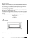
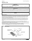
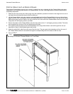
The location of the Cheese Melter controls and other components are shown in Figure 3 below.
Figure 3
Cheese Melter Operation
Chrome Rack
Removable
Grease
Drawer
Variable Adjust HI-OFF
Independent Temperature
Control Knobs
O
p
tional 4” Le
g
s
Pilot Locations
Rear Gas Supply
(
3/8” NPT Male
)
Flue Vent