


Page 14
SERVICE
This section provides procedures for testing and
replacing various major components used in this
brewer should service become necessary. Refer to
Troubleshooting
for assistance in determining the
cause of any problem.
WARNING - Inspection, testing, and repair of electri-
cal equipment should be performed only by qualified
service personnel. The brewer should be unplugged
when servicing, except when electrical tests are re-
quired and the test procedure specifically states to
plug in the brewer.
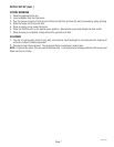
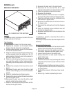
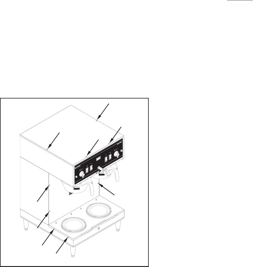
COMPONENT ACCESS
WARNING - Unplug the brewer before the removal of
any panel or the replacement of any component.
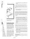
All components are accessible by the removal of
the top cover, front inspection panel and warmer base
plate.
C
A
U
T
IO
N
:
W
A
R
M
E
R
S
A
N
D
S
U
R
F
A
C
E
S
A
R
E
H
O
T
C
A
U
T
IO
N
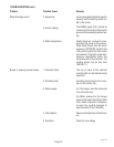
D
I
S
C
AR
D
D
E
C
A
N
T
E
R
I
F
:
.
C
R
A
C
K
E
D
.
SCR
A
T
C
HE
D
.
BO
I
L
E
D
D
RY
.
HEA
T
E
D
W
H
EN
EM
P
T
Y
.
U
S
E
D
O
N
H
I
G
H
F
L
AM
E
.
O
R
EX
P
O
S
E
D
ELEC
T
R
I
C
EL
EM
EN
TS
F
A
I
L
U
R
E
T
O
C
O
M
P
L
Y
R
I
S
K
S
IN
J
U
RY
P
N
:
658
1
9
85
B
U
NN
-
O
-
M
A
T
IC
C
O
R
P
O
R
A
TIO
N
F
U
N
NE
L
C
O
N
T
E
N
T
S
A
R
E
H
O
T
!
C
A
U
T
I
O
N
!
H
O
T
L
I
Q
U
I
D
C
A
U
T
I
O
N
!
H
O
T
L
I
Q
U
I
D
S
T
A
R
T
O
N
/
W
A
R
M
E
R
S
E
L
E
C
T
O
R
R
E
A
D
Y
R
E
A
D
Y
O
N
/
W
A
R
M
E
R
S
T
A
R
T
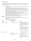
1
1
⁄2
g
a
l
1
g
a
l
1⁄
2
g
a
l
S
E
LE
C
T
O
R
1
1
⁄2
g
a
l
1
g
a
l
1
⁄
2
g
a
l
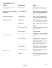
!
CAUTI
ON
HOT WATER
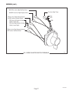
G
R
I
N
D
E
R
L
E
F
T
R
I
G
H
T
P772
27040 011904
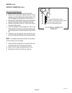
The top cover is attached with four #4-40 slotted
head screws.
The front inspection panel is attached with five #6-
32 slotted head screws.
The warmer base is attached with four #6-32
slotted head screws.
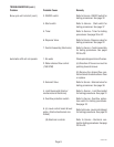
Contents
Brewer Selector Switch......................................... 16
Bypass Valve ........................................................ 15
Contactor Assembly.............................................. 18
Control Thermostat............................................... 20
Dispense Valve .....................................................22
Electronic Control .................................... 23 thru 28
Grinder Selector Switch ........................................ 28
Level Control Board and Level Probe .................... 29
Limit Thermostat .................................................. 31
ON/OFF Switch (Warmer) ..................................... 32
Overflow Protection Switch ..................................33
Relay .................................................................... 34
Solenoid ............................................................... 36
Start Switches (Brew) ........................................... 37
Tank Heaters......................................................... 38
Timers (Early Models) ..........................................39
Digital Timer (Late Models) .................................. 42
Warmer Elements ................................................. 44
Wiring Diagrams................................................... 45