


Page 4
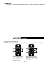
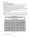
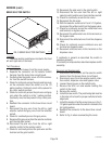
CAUTION – Improper electrical installation will damage electronic components.
1. An electrician must provide electrical service as specified.
2. Using a voltmeter, check the voltage and color coding of each conductor at the electrical source.
3. Remove the front panel beneath the sprayheads.
Models with electronic control assemblies:
Place the tank heater switch at the top of the control assembly in the “OFF” position.
Models with electro/mechanical thermostats:
Rotate the control thermostat knob fully counterclockwise to the “OFF” position.
4. Feed the cord through the strain relief and connect it to the terminal block.
5. Connect the brewer to the power source and verify the voltage at the terminal block before proceeding. Replace
the front panel.
6. If plumbing is to be hooked up later be sure the brewer is disconnected from the power source. If plumbing
has been hooked up, the brewer is ready for Initial Set-Up.
PLUMBING REQUIREMENTS
This brewer must be connected to a cold water system with operating pressure between 20 and 90 psi (138
and 620 kPa) from a
1
⁄2" or larger supply line. A shut-off valve should be installed in the line before the brewer. Install
a regulator in the line when pressure is greater than 90 psi (620 kPa) to reduce it to 50 psi (345 kPa). The water
inlet fitting is
1
⁄4" flare.
NOTE – Bunn-O-Matic recommends
1
⁄4" copper tubing for installations of less than 25 feet and
3
⁄8" for more than
25 feet from the
1
⁄2" water supply line. A tight coil of copper tubing in the water line will facilitate moving the brewer
to clean the countertop. Bunn-O-Matic does not recommend the use of a saddle valve to install the brewer. The
size and shape of the hole made in the supply line by this type of device may restrict water flow.
This equipment must be installed to comply with the Basic Plumbing Code of the
Building Officials and Code Administrators International, Inc. (BOCA)
and the Food Service Sanitation Manual of the Food and Drug Administration (FDA).
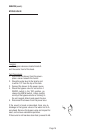
PLUMBING HOOK-UP
1. Flush the water line and securely attach it to the flare fitting on the strainer/flow control located on bottom of
brewer.
2. Turn on the water supply.
INITIAL SET-UP
CAUTION – The brewer must be disconnected from the power source throughout the initial set-up, except when
specified in the instructions.
NOTE: ECA Models Only -This brewer is equipped with a temperature sensor that indicates when to brew and, when
selected, locks-out the start of a brew cycle until the water has heated to the optimum brewing temperature.
1. Remove the front panel beneath the sprayhead.
Models with electronic control assemblies:
Place the tank heater switch at the top of the control assembly in the “OFF” position.
Replace the front panel.
Models with electro/mechanical thermostats:
Rotate the control thermostat knob fully counterclockwise to the “OFF” position.
Replace the front panel.
2. Connect the brewer to the power source. Water will begin flowing into the tank.
3. When water stops flowing into the tank, remove the front panel and proceed as directed:
27040 032201
Electrical Hook-Up