


Page 25
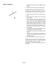
YES
YES
YES
YES
NO
NO
NO
NO
YES
NO
NO
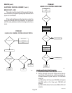
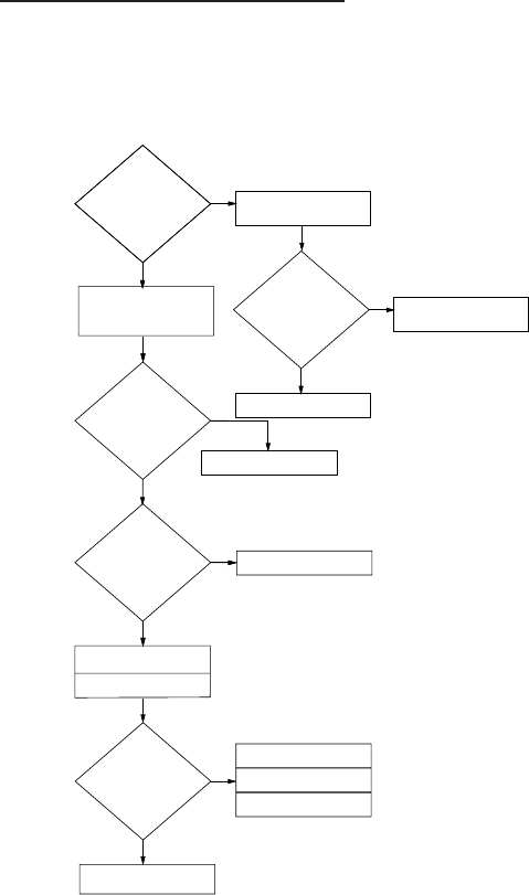
MEASURE VOLTAGE
AT TANK HEATER (5)
VOLTAGE PRESENT
REPLACE TANK
HEATER (5)
LIMIT THERMOSTAT (6)
OK
?
REPLACE LIMIT
THERMOSTAT (6)
REPLACE CONTROL
ASSEMBLY (1)
MEASURE VOLTAGE
AT TANK HEATER (5)
VOLTAGE PRESENT
REPLACE TRIAC (17)
CHECK FOR SPLIT
TANK HEATER (5)
REINSTALL ORIGINAL
CONTROL ASSEMBLY (1)
RECHECK WATER
TEMPERATURE
LED ON CONSTANTLY
TURN TEMPERATURE
ADJUSTING SCREW (16)
CLOCKWISE CONTINUOUSLY
LED ON
?
REPLACE CONTROL
ASSEMBLY (1)
ADJUST FOR CORRECT
WATER TEMPERARURE
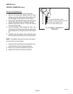
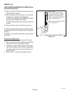
3. Disconnect brewer from the power source.
If voltage was present as described, proceed to #4.
If voltage was not present as described, refer to the
Wiring Diagrams
and check brewer wiring harness.
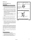
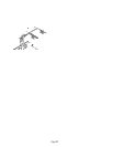
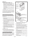
4. Remove the pink wire from terminal 5 of the
electronic control assembly (1).
5. With a voltmeter, check the voltage across termi-
nals 1 & 4 of the electronic control assembly (1).
Connect brewer to the power source. The indica-
tion must be:
a.) 208 volts ac for three wire 120/208 volt models
and 240 volts ac for three wire 120/240 volt
models after a delay of approximately 1 second.
b.) 200 to 240 volts ac for two wire 200 or 240 volt
models after a delay of approximately 1 second.
6. Disconnect the brewer from the power source.
If voltage was present as described, the liquid level
control system is operating properly, proceed to #7.
If voltage was not present as described, replace the
electronic control assembly (1) and temperature sen-
sor (8) in the tank lid.
NOTE - each electronic control assembly is calibrated
to a temperature sensor. Both components MUST be
replaced as a set.
7. Reconnect the pink wire to terminal 5 of the
electronic control assembly (1).
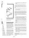
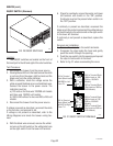
8. Remove the liquid level probe (7) from the tank lid,
and inspect it for mineral deposits. Replace it if
necessary. Keep the exposed ends of the probe
away from any metal surface of the brewer.
9. With a voltmeter, check the voltage across termi-
nals 1 & 4 of the electronic control assembly (1).
Connect the brewer to the power source. The
indication must be:
a.) 208 volts ac for three wire 120/208 volt models
and 240 volts ac for three wire 120/240 volt
models after a delay of approximately 1 second.
b.) 200 to 240 volts ac for two wire 208 or 240 volt
models after a delay of approximately 1 second.
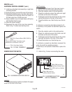
10. Touch the screw head end of the probe to the
brewer housing. The indication must be 0.
11. Move the probe away from the brewer housing.
The indication must again be:
a.) 208 volts ac for three wire 120/208 volt models
and 240 volts ac for three wire120/240 volt
models after a delay of approximately 1 second.
b.) 200 to 240 volts ac for two wire 200 or 240 volt
models after a delay of approximately 1 second.
12. Disconnect the brewer from the power source.
If voltage was present as described, reinstall the
probe, the sensing function of the system is operating
properly.
If voltage was not present as described, check the pink
probe wire and the green ground wire for continuity
and/or replace the probe.
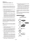
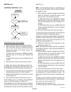
Temperature Control Flow Charts
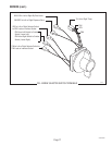
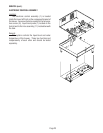
SERVICE (cont.)
ELECTRONIC CONTROL ASSEMBLY (cont.)
P810
PROBLEM:
WATER NOT HOT ENOUGH
27040 041100