


Page 18
SERVICE (cont.)
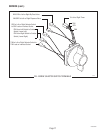
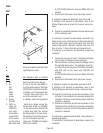
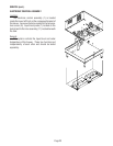
CONTACTOR ASSEMBLY
Location:
The contactor assembly is located inside the hood
just to the rear of the right dispense valve.
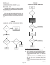
Test Procedures:
Mechanical Thermostat (Brewers with or without
Recovery Booster)
1. Disconnect the brewer from the power source.
2. Disconnect the red wire of the two pole 200V or
240V terminal block or the white wire of the three
pole 120/208V or 120/240V terminal block and the
black wire of the contactor coil. Disconnect the
black wire of the control thermostat from the
remaining black wire of the contactor coil.
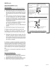
3. Gently remove the capillary bulb and grommet
from the tank.
4. With a voltmeter, check the voltage across the
white wire from the terminal block on 120/208,
120/240 volt units or the red wire from 200 or 240
volt units and the black wire from the control
thermostat when the thermostat is turned clock-
wise to the "FULL ON" position. Connect the brewer
to the power source. The indication must be:
a.) 120 volts ac for three wire 120/208 volt models
and three wire 120/240 volt models.
b.) 200 to 240 volts ac for two wire 200 or 240 volt
models.
5. Disconnect the brewer from the power source.
If voltage is present as described, proceed to #6.
If voltage is not present as described, refer to the
Wiring Diagrams
and check the brewer wiring har-
ness.
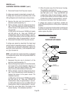
6. Check for continuity between the two black wires
of the contactor coil.
If continuity is present as described, reconnect one
black wire to red or white wire from the terminal block
and the other black wire to the black wire from the
control thermostat. Reinstall capillary tube into the
tank to a line 7" above the bulb and proceed to #7.
If continuity is not present as described, replace the
contactor.
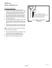
7. Locate the red wire on the L1 terminal and black
wire on the L2 terminal on the contactor.
8. With a voltmeter, carefully check the voltage across
the red and black wires. The indication must be:
a.) 208 volts ac for three wire 120/208 volt models
and 240 volts ac for three wire 120/240 volt
models.
b.) 200 to 240 volts ac for two wire 200 or 240 volt
models.
9. Disconnect the brewer from the power source.
If voltage is present as described, proceed to #10.
If voltage is not present as described, refer to the
Wiring Diagrams
and check brewer wiring harness.
10. Check for continuity across the terminals on the
left side of the contactor by manually closing the
contacts. Continuity must not be present when the
contact is released.
11. Check for continuity across the terminals on the
right side of the contactor by manually closing the
contacts. Continuity must not be present when the
contact is released.
If continuity is present as described, the contactor is
operating properly.
If continuity is not present as described, replace the
contactor.
P796
!
C
A
U
TIO
N
H
O
T
WA
T
E
R
.
M
IN
U
T
E
S
B
U
N
N
-
O
-M
A
T
I
C
P
/
N
2
6
2
0
-
1
2
0
V
A
C