Page 28
P787
SERVICE (cont.)
ELECTRONIC CONTROL ASSEMBLY (cont.)
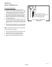
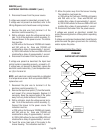
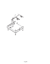
11. Install new triac/heat sink assembly on right tank
mounting bracket.
12. Route the wires up around the rear of the brewer.
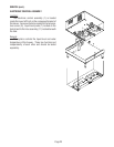
13. Reinstall the bottom cover, four feet, tank mount-
ing brackets and triac/heat sink to the bottom of
the tank using four #10-32 keps nuts.
14. Secure bottom cover to brewer base with twelve
#8-32 slotted head screws.
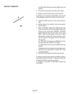
15. Stand the brewer upright.
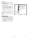
16. Reconnect the wires of the new triac assembly.
Refer to Fig. 13 when reconnecting wires.
P785
S
T
A
R
T
O
N
/ W
A
RM
ER
SEL
ECTO
R
R
EADY
R
EAD
Y
O
N
/ W
A
RM
E
R
S
T
A
R
T
1
1
⁄
2
gal1
gal
1
⁄
2
gal
SEL
ECTO
R
1
1
⁄
2
gal
1
gal
1
⁄2
gal
P786
GRINDER SELECTOR SWITCH
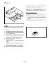
Location:
The grinder selector switch is located in the upper
center on the front of the hood.
27040 032201
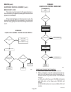
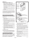
FIG. 13 TRIAC TERMINALS
FIG. 14 GRINDER SELECTOR SWITCH
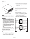
FIG. 15 GRINDER SELECTION
SWITCH TERMINALS
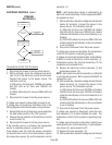
Test Procedure:
1. Disconnect the brewer from the power source.
2. Remove all wires from the switch terminals.
3. Place the selector switch in the left position.
4 Check for continuity across the center and right
terminals on the rear of the switch.
5. Continuity must not be present across the center
and left terminals on the rear of the switch.
6. Check the bottom row, then the top row of termi-
nals.
If continuity is present as described proceed to #7.
If continuity is not present as described replace the
switch.
7. Place the selector switch in the right position.
8. Check for continuity across the center and left
terminals on the rear of the switch.
9. Continuity must not be present across the center
and right terminals on the rear of the switch.
10. Check the bottom row, then the top row.
If continuity is present as described, reconnect the
wires, the switch is operating properly.
If continuity is not present as described, replace the
switch.
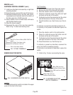
11. Refer to Fig. 15 when reconnecting the wires.
PNK to PNK Lead from
Right Brew Selector Switch
PNK to PNK Lead from Interface
Socket
PNK to PNK Lead from
Left Brew Selector Switch
WHI/VIO to Terminal Block (200V-240V Red
Insert)
BLU to Right Tank Heater (Left)
BLU to Electronic Control #7
TAN to Tank Heater Switch


