


15
solenoid with a voltmeter. Connect the grinder to
the power source and place the Off/On/Start switch
in the “ON” center position. The indication must be
120 volts AC.
4. Disconnect the grinder from the power source.
If voltage is present as described, proceed to #5.
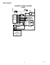
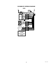
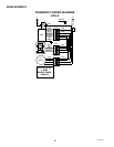
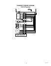
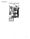
If voltage is not present as described, refer to the
wiring diagram and check grinder wiring harness.
5. Check for continuity across the solenoid coil ter-
minals.
If continuity is present as described, reconnect the
violet wire and the red wire on the right solenoid or the
orange wire and the red wire on the left solenoid.
If continuity is not present as described, replace the
solenoid.
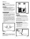
6. Check the solenoid for coil action when the Off/On/
Start switch is momentarily pressed to the “START”
(lower) position and released. Connect grinder to
the power source. Watch the slide gate open and
close as the coil magnet attracts and after a period
of time, releases the plunger.
7. Disconnect the grinder from the power source.
If the slide gate functions as described the solenoid is
operating correctly.
If the slide gate does not function as described, replace
the solenoid.
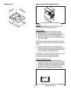
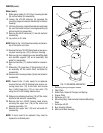
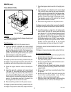
Removal and Replacement: Refer to Fig. 18
1. Loosen the two #8-32 pan head screws securing
the timer mounting bracket to motor support.
2. Move timer bracket, timer and rear cover (1) away
from the rear of the left solenoid.
3. Remove the shoulder screw (2) securing the sole-
noid to the solenoid mounting plate (6). Set aside
for reassembly.
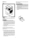
4. Slide solenoid (4) and solenoid mounting bracket
(3) off of the solenoid plunger (5).
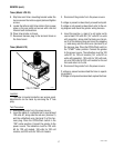
5. Remove the four #8-32 truss head screw securing
the solenoid (4) to the solenoid mounting bracket
SERVICE (cont.)
Solenoid (cont.)