


9
SERVICE (cont.)
Capacitor (Model LPG)(cont.)
Location:
The capacitor is located inside the front panel of
the hopper housing next to the Off/On/Start switch.
Test Procedure:
1. Disconnect grinder from the power source.
2. Visually inspect the capacitor for leakage. If leak-
age is visible, replace the capacitor.
3. Connect the grinder to the power source, if the
motor does not run, disconnect the capacitor
wiring harness from the main wiring harness. If
the motor now runs, replace the capacitor.
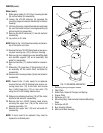
Removal and Replacement:
1. Disconnect the capacitor wiring harness from the
main wiring harness.
2. Remove the #8-32 nut attaching the capacitor and
mounting bracket to the hopper housing and re-
move the bracket, shield, capacitor and capacitor
wiring harnes as an assembly.
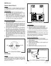
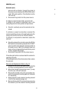
3. Disconnect the wiring harness from the capacitor
and attach it to a new capacitor making sure the
black wire attaches to the positive (+) pole, FIG. 4.
4. Wrap the shield around the capacitor and place
into the mounting bracket. Slide the lower tab of
the mounting bracket between the wrapper and
base and secure in place over the mounting stud
with the #8-32 nut.
5. Reconnect the wiring harness to the main wiring
harness.
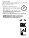
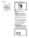
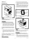
Circuit Breaker
Location:
The circuit breaker is located on the rear of the
grinder next to the power cord strain relief bushing.
The circuit breaker is not available on Model LPG
equipped with capacitor.
P1036
FIG. 5 CIRCUIT BREAKER
27103.0000C 11/98 © 1996
BUNN-O-MATIC CORPORATION
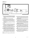
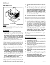
SCHEMATIC WIRING DIAGRAM
LPG2E
NL1
BLK
RED
WHI
120 VOLTS AC
2 WIRE
SINGLE PHASE
60 HZ
GRN
3
AMP
2
3
4
5
6
1
7
8
9
10
TIMER ASSY.
(Hopper Slide
Gate Timer
Dial Wiring)
Right - Brown
Left - Orange
YEL
WHI
BLU
YEL
WHI/BLK
BLK
RED
VIO
ORA
OFF/ON/START
SWITCH
RED
RED
RED
GRN
SELECTOR
SWITCH
WHI
RED
RED
WHI
BLK
GRINDER
SLIDE GATES
RT
SOL
LT
SOL
RED RED
M
Test Procedure:
1. Disconnect grinder from the power source.
2. Remove the wires from the circuit breaker.
3. Check for continuity between the terminals. Con-
tinuity must be present between the terminals.
If continuity is present as described the circuit breaker
is functioning properly.
If continuity is not present as described, press reset
button and repeat step #3, if continuity is not present
as described, replace the circuit breaker.
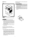
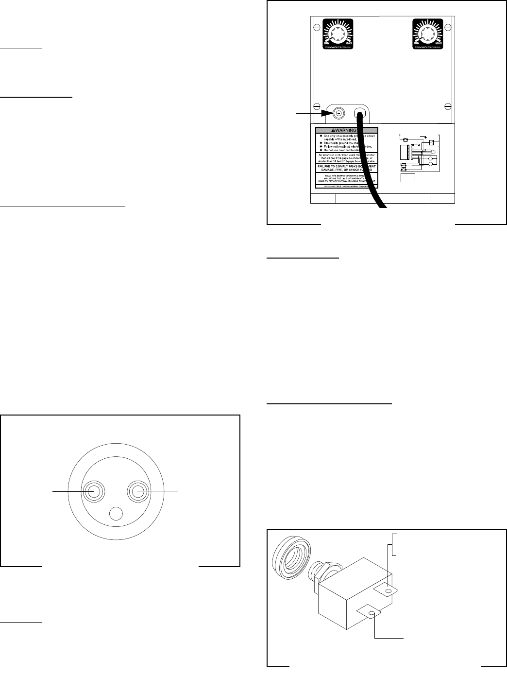
Removal and Replacement:
1. Remove the wires from the circuit breaker.
2. Remove the face nut securing circuit breaker to the
motor support.
3. Remove circuit breaker.
4. Install new circuit breaker in motor support and
secure with face nut.
5. Reconnect the wires.
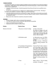
6. Refer to FIG. 6 when reconnecting the wires.
P1037
FIG. 6 CIRCUIT BREAKER TERMINALS
P1747
FIG. 4 CAPACITOR TERMINALS
+
BLK
WHI/BRN
RED from Motor-LPG-2E
BLK from Start Switch-LPG
BLK from Power Cord
27091 111598