


16
SERVICE (cont.)
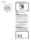
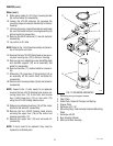
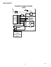
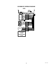
Timer (Model LPG-2E)
P1061
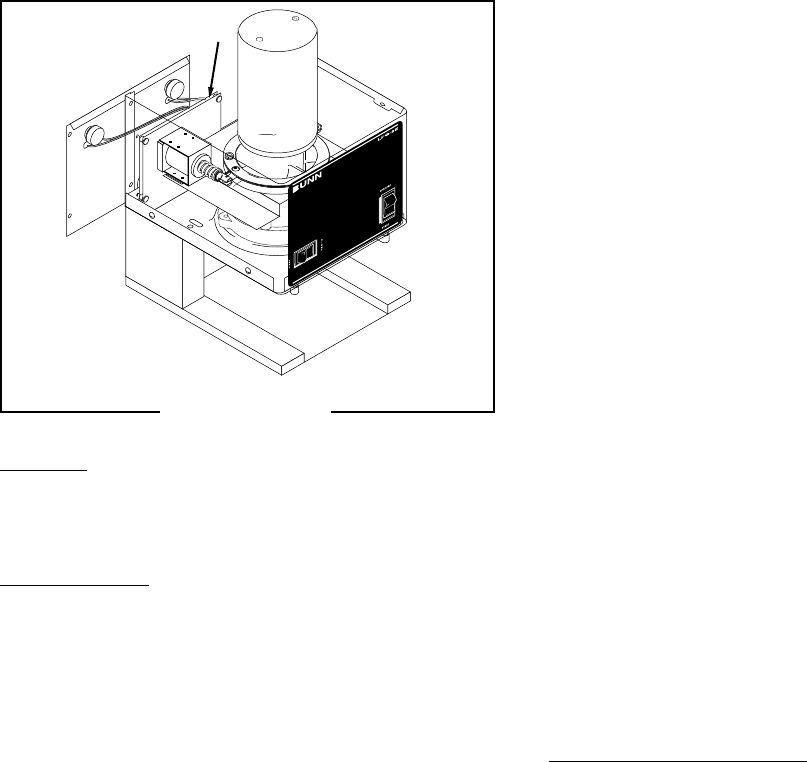
Location:
The timer is located inside the hopper housing just
behind the left solenoid.
Test Procedure:
1. Disconnect grinder from the power source.
2. Insert the leads of a voltmeter set to read at least
120 volts AC, along side the red wire (terminal 8)
and the white wire (terminal 2) of the harness plug.
Place the Off/On/Start switch in the “ON” center
position. Connect the grinder to the power source.
The indication must be 120 volts AC.
3. Disconnect the grinder from the power source.
If voltage is present as described, proceed to step #4.
If voltage is not present as described, refer to the wir-
ing diagram and check the grinder wiring harness.
4. Place the hopper selector switch in the left posi-
tion.
5. Insert the leads of a voltmeter set to read at least
120 volts AC, along side the red wire (terminal 8)
and the orange wire (terminal 10) of the harness
plug. Place the Off/On/Start switch in the “START”
lower position. Connect the grinder to the power
source. The indication must be 120 volts AC for
the set gate time and return to 0 volts.
6. Disconnect the grinder from the power source.
If voltage is present as described, proceed to step #7.
If voltage is not present as described, replace the timer.
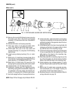
FIG. 20 TIMER
7. Place the hopper selector switch in the right posi-
tion.
8. Insert the leads of a voltmeter set to read at least
120 volts AC, along side the red wire (terminal 8)
and the violet wire (terminal 9) of the harness plug.
Place the Off/On/Start switch in the “START” lower
position. Connect the grinder to the power source.
The indication must be 120 volts AC for the set
gate time and return to 0 volts.
9. Disconnect the grinder from the power source.
If voltage is present as described, proceed to step#10.
If voltage is not present as described, replace the timer.
10. Insert the positive (+) lead of a volt meter set to
read at least 120 volts DC, along side the black
wire (terminal 7) of the harness plug and insert
the negative (-) lead along side the white/black
wire (terminal 6) of the harness plug. Place the
Off/On/Start switch in the “START” lower position.
Connect the grinder to the power source. The in-
dication must be 120 volts DC for the set gate
time plus clean out time and return to 0 volts.
If voltage is present as described the timer is operat-
ing properly.
If Voltage is not present as described, replace the timer.
Removal and Replacement:
1. Disconnect the main wiring harness plug from the
terminal block on the timer.
2. Remove the two timer dial knobs located on the
rear panel of the grinder.
3. Remove nut and internal tooth lockwasher secur-
ing dials to the rear panel.
4. Loosen the two #8-32 pan head screws securing
the timer and timer mounting bracket to the motor
support plate.
5. Remove timer and timer mounting bracket from
the grinder.
6. Remove the four #6-32 keps nuts securing the
timer to the mounting bracket. Leave the four
spacers on the mounting bracket studs.
7. Place new timer over the studs on the mounting
bracket and secure with four #6-32 keps nuts.
27091 111598