


5
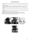
INITIAL SET-UP
1. Apply the four non-skid pads from the parts box to the bottom of the legs.
2. Remove the drip tray assembly and drip tray bracket from the parts box.
3. Place a set of key holes in the drip tray bracket over the lower two screws in the panel below the hopper ac-
cess door; push down gently and tighten screws.
ELECTRICAL REQUIREMENTS
CAUTION - The dispenser must be disconnected from the power source until specified in Electrical Hook-Up.
The dispenser can be wired to a 120V, 2 wire with ground.
Refer to the dispenser’s dataplate for exact voltage requirements.
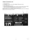
ELECTRICAL HOOK-UP
CAUTION – Improper electrical installation will damage electronic components.
1. An electrician must provide electrical service as specified.
2. Using a voltmeter, check the voltage and color coding of each conductor at the electrical source.
3. Connect the dispenser to the power source.
4. Place the main power switch in the "ON" position.
5. If plumbing is to be hooked-up later be sure the dispenser is disconnected from the power source. If plumb-
ing has been hooked-up, the dispenser is ready for Initial Fill & Heat.
PLUMBING REQUIREMENTS
This dispenser must be connected to a cold water system with operating pressure between 20 and 100 psi (138
and 690 kPa). This water source must be capable of producing a minimum flow rate of 4.5 fl. oz. (133.1 ml) per
second. A shut-off valve should be installed in the line before the dispenser. Install a regulator in the line when
pressure is greater than 100 psi (690 kPa) to reduce it to 50 psi (345 kPa). The water inlet fitting is .25" (9.52
mm) flare.
NOTE - At least 18 inches (457 mm) of an FDA approved flexible beverage tubing, such as reinforced braided
polyethylene or silicone, before the dispenser will facilitate movement to clean the countertop. Bunn-O-Matic
does not recommend the use of a saddle valve to install the dispenser. The size and shape of the hole made in
the supply line by this type of device may restrict water flow.
PLUMBING HOOK-UP
1. Flush the water line and securely attach it to the flare fitting on the bottom of the dispenser.
2. Turn-on the water supply.
NOTE - If a backflow prevented is required by code, a shock arrestor should be installed between backflow preventer
and dispenser. Installing the shock arrestor as close to the dispenser as possible will provide the best results.
39328.3 012113
NOTE - Water pipe connections and fixtures directly connected to a potable water supply shall be sized, installed
and maintained in accordance with federal, state and local codes.
As directed in the International Plumbing Code of the International Code Council and the Food
Code Manual of the Food and Drug Administration (FDA), this equipment must be installed with
adequate backflow prevention to comply with federal, state and local codes. For models installed
outside the U.S.A., you must comply with the applicable Plumbing /Sanitation Code for your area.