


HEADER
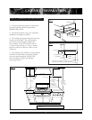
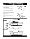
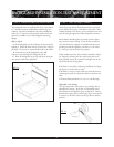
The backguard must be installed when there is less than a
12” clearance between combustibles and back edge of
cooktop. For island installations and other installations
with over 12” clearance, and optional stainless steel trim
channel is available to cover the backguard mounting
flanges.
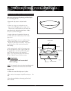
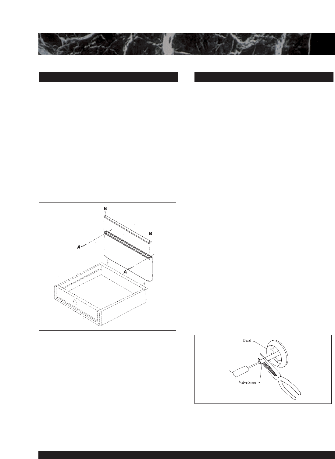
Refer to Fig.12
A. Slide backguard over the 2 flanges on the rear of the
appliance. Fasten the back with two screws (See A Fig.12)
provided. No screws are required behind the wok section.
B. Fasten the top of the backguard to the wall
with two screws through the backguard (See B.).
C. Place the backguard cap on top and fasten using the
two counter-sunk screws provided.
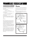
Check for proper burner flame characteristics and adjust
the air shutter if necessary. Each burner and valve is indi-
vidually checked at the factory prior to shipment but varia-
tions in local gas supply may make adjustment necessary.
Burner flames should be blue and stable with no yellow
tips, excessive noise or lifting. If any of these conditions
exist, check that the regulator is installed with the arrow
pointing towards the appliance, and that it is 5.0 inches
w.c. Nat. gas; and 10.0 inches for propane.
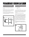
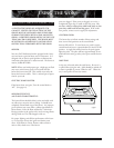
If this condition persists, the air shutters should be adjust-
ed. Begin by removing the valve panel using the access
hole provided, loosen the air shutter locking screw on the
face of the burners mixing head.
If the flame is too yellow, indicating insufficient air, adjust
the shutter to increase the air inlet.
If the flame is noisy or tends to lift away from the burner,
indicating too much air, adjust the shutter to decrease the
inlet.
The burner flame should be 1-1/2 to 2-1/2 inches high.
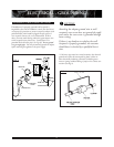
Adjustable - Low Setting:
The open top burner valve used on your cooktop has an
adjustable low setting. Each valve is individually tested
and adjusted on the appliance prior to shipment. Due to
fluctuations in gas pressure and heating valve, you may feel
it necessary to increase or decrease the gas flow at the low
position.
STEP 7: TEST & ADJUSTMENTSTEP 6: BACKGUARD INSTALLATION
8
BACKGUARD INSTALLATION-TEST & ADJUSTMENT
FIG. 12
FIG. 13