


PLACING & ANCHORING - ELECTRICAL
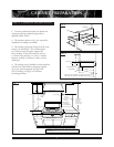
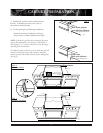
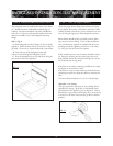
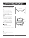
Lift and place the cooktop in the opening. Be careful not to
pinch the power cord or gas inlet between anything. Anchor
the cooktop; ensure that the appliance is in place and level
(See Fig.7).
For cabinets with side access, screw the 2 “L” shaped brackets
(supplied) into the holes provided using the #10 sheet-metal
screws as shown in Fig.7 cooktop. Then using the 1/4 - 20
bolt and nuts (supplied), anchor as shown.
For cabinets with no side access, first fasten the brackets to
the cabinet side wall using a suitable fastener. Then drill two
5/32” dia. holes upward into the bottom of cooktop and fas-
ten as shown in Fig 7. countertop.
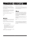
POWER REQUIREMENTS:
120 VAC, 60 Hz.
7 Amp.
(Use 15 Amp. Circuit)
Always disconnect electric supply cord from the wall outlet or
service disconnect before servicing this appliance. Observe all
governing codes and ordinances when grounding, in absence
of which, observe National Electrical Code ANSI / NFPA
No. 70-1987.
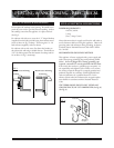
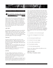
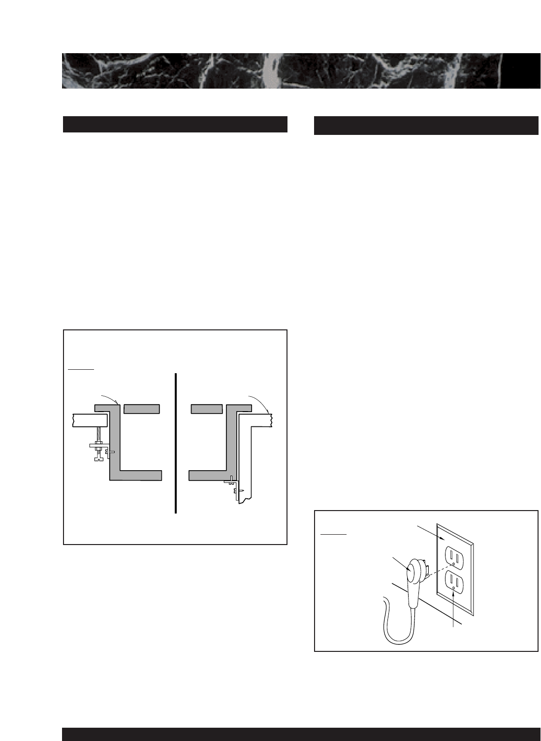
RECOMMENDED GROUNDING METHOD
This appliance is factory equipped with a power supply cord
with a three-prong grounding plug (with polarized parallel
blades). It must be plugged into a mating grounding, type
receptacle, connected to a correctly polarized 120 Volt circuit.
If the circuit does not have a grounding type receptacle, it is
the responsibility and obligation of the installer or user to have
the existing receptacle changed to a properly grounded and
polarized receptacle in accordance with all applicable local
codes and ordinances by a qualified electrician. In the
absence of local codes and ordinances the receptacle replace-
ment shall be in accordance with the National Electrical
Code.
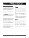
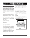
THE THIRD PRONG SHOULD NOT, UNDER ANY
CIRCUMSTANCES, BE CUT OR REMOVED (See Fig. 8).
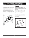
(See Fig. 9).
Receptacle Box
Cover Plate
Three Prong
Receptacle
Three
Prong
Plug
610 fi 23
STEP 4: ELECTRICAL CONNECTIONS
Side access anchoring:
777fig09
Bottom access anchoring:
Cooktop Countertop
STEP 3: PLACING & ANCHORING
5
FIG. 7
FIG. 8