


1. To ensure professional results, the cabinet and
countertop openings should be prepared by a
qualified cabinet worker.
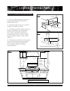
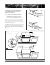
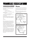
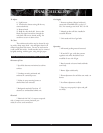
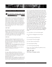
2. The clearances shown in Fig.1 are required for
installations of cooktop and islands.
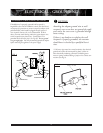
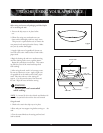
3. The cooktop is designed to hang from the coun-
tertop by its side flanges. The countertop how
ever, must be strong enough to support this
heavy cooktop. It may be necessary to add a 2
x 4 corner brace (See Figs.3, 4, and 5). Another
alternate would be to construct a deck to set the
cooktop on.
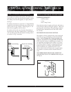
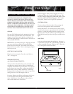
4. The cooktop can be installed in various positions
with the front either flush or projecting, depend-
ing on the countertop depth. (See Fig.2 side
view of cooktop; see Figs.3-5 for alternate
mounting positions.)
9"
12"
22-5/8"
26-3/8"
23-3/8"
3" To Center Line
of Gas Inlet
3/4"
1/2"
Cabinet face for installation with projecting control panel
Cabinet face for installation with flush control panel
2"
Countertop level
777fig07
Counter-Sunk Screws
CABINET PREPARATION
3
STEP 2: COOKTOP INSTALLATION
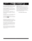
VENT HOOD
12" Min. to
Combustible
Material ,
Each Side
WALL
18" Min.
30" Min.,
36" Max.
0" Bottom Clearance
0" Side Cutout Clearance
0" Rear Clearance
(w/ backguard)
12" (w/out backguard)
3" min each side
counter top level
777fig12
CAUTION:
36" Min. to
combustible
material , from
cooking surface
13"
Min.
as defined in the "National Fuel Gas Code" (ANSI Z223.1, Latest Editon).
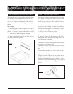
> The level of the cooktop top must be at the same level or above the
countertop level.
FIG. 1
FIG. 6
FIG. 2