


HEADER
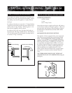
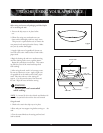
To Adjust:
1) Light burner.
2) Turn knob to lowest setting (all the way
counterclockwise).
3) Remove knob.
4) Hold the valve shaft still. Insert a thin
blade, flat-tipped screwdriver through the
valve shaft and turn to desired setting. Be
careful not to turn it down so low.
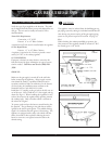
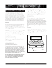
To Clean:
The stainless steel surface may be cleaned by wip-
ing with a damp soapy cloth. Any mild glass cleaner will
remove fingerprints and smears. Do not use steel wool as
it will scratch this surface. Small scratches may be removed
by lightly sanding, with the grain, using 100 grit paper.
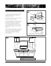
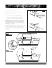
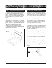
Placement of Unit:
Specified clearances maintained to cabinet
surfaces.
Cooktop correctly positioned and
anchored in countertop recess.
Nylon tie straps securing burner to
channel have been removed.
Backguard attached if less than 12”
clearance to combustibles behind unit.
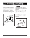
Electrical:
Polarized 120 VAC, 15 ampere receptacle
with 15 ampere over current protection pro-
vided, for service cord connection.
Gas Supply:
Pressure regulator (shipped with unit)
connected to manifold and is set for 5.0”
W.C. for natural gas and 10.0” W.C. for LP.
Manual gas shut off valve installed in
accessible location.
Unit tested and free of gas leaks.
Operation:
All internal packing material removed.
If used of LP gas, verify that pressure
regulator and orifice hoods have been
modified for use with LP gas.
Bezel centered on burner knob and knob
turn freely.
Burner lights satisfactorily.
Flame adjustment for soft blue cone made on
burner.
Low flame adjustment verified.
Drip trays are properly in place and pull
out freely.
STEP EIGHT: INSTALLER FINAL CHECKLIST
9
FINAL CHECKLIST