


INSTALLATION PROCEDURES Eskimo Ice Installation & Operation Manual
8 L-3152 ENGLISH
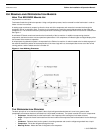
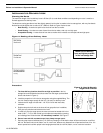
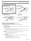
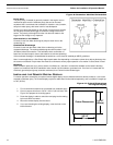
INSTALLING THE ICE-LEVEL SENSOR
To prevent overflow, this sensor stops ice production when the ice in the storage box reaches the level of the sensor. Use
Figure 6 below to determine placement for the ice-level sensor at the storage box location.
1. The sensor must be located 2.5” (64mm) minimum to 3” (76mm) maximum to the left or right side of the ice-delivery
hole. Drill a 23/32" (19mm) hole for sensor.
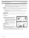
2. Use the 2 lock nuts provided to secure sensor into the hole.
3. Use marine-grade sealant around the hole if desired. (Remember that the unit may have to be removed at some time.)
4. Route the cable to the ice maker’s electrical box and plug the end into the ice-bin sensor socket. See the appropriate
electrical wiring diagram in this manual for the voltage model you are using.
Figure 6: Location of Ice-Level Sensor (front view)
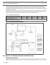
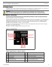
INSTALLING THE FEEDWATER SYSTEM
Feedwater for the unit should be fresh water supplied by the boat’s potable water system. The water reservoir has a float switch
to ensure the unit does not operate without a water supply.
Requirements
• Supplied feedwater must have a pressure of at least 15 PSI.
• The water system must be able to supply at least 4 GPH when the ice maker is operating.
• Install the in-line filter (supplied in kit) just prior to the unit to remove sediment which may clog the needle valve in the
water reservoir.
• Dometic recommends installing a shut-off valve in the feedwater line between the source and the filter to facilitate filter
changes.
WARNING
Use of saltwater as feedwater will damage auger components and evaporator barrel and will void the
warranty.
WARNING
Failure to install and use the water filter included with the installation kit will void the warranty.
Note, if unit is purchased separately you must also purchase the water filter to maintain warranty.
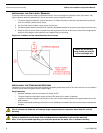
Mount the ice-delivery
hose as high as possible
in the ice-storage box.