


INSTALLATION PROCEDURES Eskimo Ice Installation & Operation Manual
12 L-3152 ENGLISH
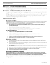
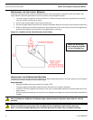
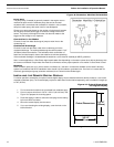
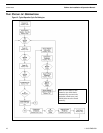
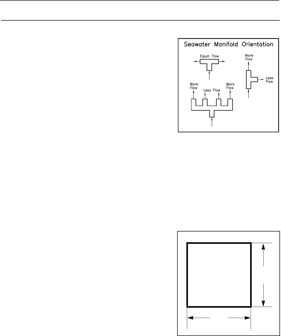
Figure 9: Seawater Manifold Orientation
Pump Relay
The pump relay (if needed) is generally located in the engine room or
mechanical space near the seawater pump, but can be mounted
anywhere that is convenient and accessible. It must be in a dry location,
away from water spray, with some room for heat dissipation.
Choose your pump relay based on the number of units that will operate
off one pump. Choose each trigger to reflect the voltage of the unit it
serves. The polarity of the signal from the unit does not matter to the
trigger, but the voltage is very important.
Connection to Ice Maker
Connect a hose from water discharge of pump to water inlet on the
condensing coil.
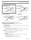
Overboard Discharge
Connect a hose from the water outlet of the condensing coil to the
overboard discharge. The overboard discharge should be located 1” to 2”
(25-50mm) above the waterline. This facilitates visual confirmation of
water flow and also keeps it close to the waterline to minimize splashing.
If the overboard discharge is located below the waterline a valve must be installed per ABYC guidelines.
Note: In some applications a Sea Chest might impede water flow depending on the water volume other devices discharge into
the common overboard. Proper water flow must be confirmed to ensure proper operation of ice maker if a Sea Chest is used.
Bonding
Bond all metallic parts (thru-hull, valves, strainer, manifolds, etc.) that are in contact with seawater to the vessel’s bonding
system in accordance with ABYC standards. Items should only be bonded or grounded once. If an item is in contact with an
electrically grounded part (pump, seawater condenser) then it should not be bonded again.
INSTALLING THE REMOTE DIGITAL DISPLAY
For easier operation accessibility, an optional remote digital display may be installed wherever desired, however, it can not be
exposed to saltwater spray. The remote display requires a cable that must be ordered separately, and is available in lengths up
to 100’ (30.5m).
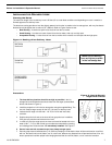
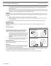
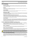
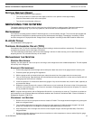
Figure 10: Cutout Dimensions
For Digital Display
1. Find a convenient location that is protected from saltwater spray.
2. Cut out a square hole that is 3-3/16” x 3-3/16” (82 x 82 mm). See
Figure 10 to prepare the mounting space.
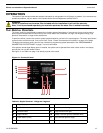
3. Route the display’s cable to control box and plug into the mating
8-pin male RJ45 connector.
4. Mount the remote display into the cutout.
5. If you are relocating the existing display, cover the hole on the
back of the box.
3-3/16”
(82mm)
3-3/16”
(82 mm)
Cutout Dimensions
Note: Image shown is not to scale.