


5
INSTALLATION
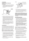
VENTILATION
The installation shall be made in such a manner as to
separate the combustion system from the living space
of the mobile home or recreational vehicle. Openings
for air supply or for venting of combustion products shall
have a minimum dimension of not less than 1/4 inch.
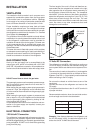
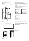
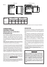
Proper installation requires one lower fresh air intake
and one upper exhaust vent. The ventilation kits shown
in this instruction manual have been certified for use with
the refrigerator models listed in the table. For “Certified
Vent System Kits” see page 19.
The ventilation kits must be installed and used without
modification. An opening toward the outside at floor level
in the refrigerator compartment must be provided for
ventilation of heavier-than-air fuel gases. The lower vent
of the recommended kits is provided with proper size
openings. The flow of combustion and ventilating air must
not be obstructed.
The lower side vent is fitted with a panel, which provides
an adequate access opening for ready serviceability of
the burner and control manifold of the refrigerator. This
should be centered on the back of the refrigerator.
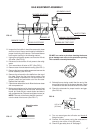
GAS CONNECTION
Hook up to the gas supply line is accomplished at the
manual gas valve, which is furnished with a 3/8" SAE
(UNF 5/8" -18) male flare connection. All completed con-
nections should be checked for leaks with soapy water.
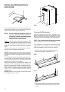
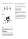
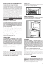
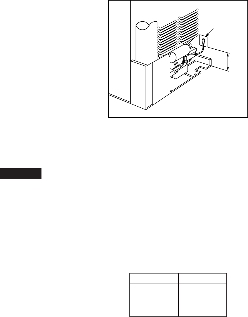
The free length of the cord is 2 feet and therefore rec-
ommended that the receptacle be located to the right
side (opposite side of refrigerator burner assembly) of
the refrigerator (viewed from the rear). The receptacle
should be 3” (from the bottom of the plastic receptacle)
above the refrigerator mounting floor. (see FIG. 3). This
allows easy access through the vent door. The cord
should be routed to avoid direct contact with the burner
cover, flue cover or any other components that could
damage the cord insulation.
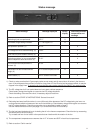
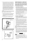
12 Volts DC Connection
The refrigerator model NDA 1402 require a continuous
12 volt DC supply to maintain the automatic energy se-
lector system and the auto defrost control system to func-
tion.
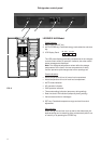
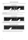
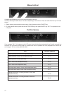
The connection is made to the positive (+) and negative
(-) terminals of the terminal block on the back of the re-
frigerator. (See FIG. 1). Correct polarity must be observed
when connecting to the DC supply.
Do not use the chassis or vehicle frame as one of the
conductors.
Connect two wires at the refrigerator and route to the
DC supply.
It is important that the wires to the 12-volt DC terminal is
of proper wire size.
Recommended conductor wires size and total conduc-
tor wires length are found in the table below.
! WARNING
120 Volt AC
receptacle
3’’
FIG. 3
DO NOT use a flame to check for gas leaks.
The gas supply system must incorporate a pressure regu-
lator to maintain a supply pressure of not more than 11
inches water column.
When testing the gas supply system at test pressures in
excess of 1/2 psi, the refrigerator and its individual shut
off valve must be disconnected from the gas supply pip-
ing system.
When testing the gas supply system at pressures less
than or equal to 1/2 psi, the appliance must be isolated
from the gas supply piping system by closing its indi-
vidual manual shut off valve.
In case detailed instructions on the installation and con-
nection to the gas supply are required, contact your
dealer or distributor.
ELECTRICAL CONNECTION
120 Volts AC Connection
The refrigerator is equipped with a three-prong (ground-
ing) plug for your protection against shock hazards and
should be plugged directly into a properly grounded three-
prong receptacle. DO NOT cut or remove the grounding
prong from this plug.
Length Minimum Wire Size
<33 ft. (<10m) 12 AWG
33 - 66 ft. (10 - 20m) 10 AWG
>66 ft. (>20m) 8 AWG
Example: If the distance between the refrigerator and
the 12V DC supply is 20 ft., the total wire length is 40 ft.
and a wire size of 10 AWG should be used.